Join my Blender 3D forum, where you can network with other Blender friends and get your Blender 3D questions answered.
In my tutorial on world background colors, we saw how to change the background color, produce a gradient from one color to another as a background to the scene, and how to map the colors to the world horizon and zenith.
Blender also lets you use an entire image, such as a sky image, as a background. In addition, if you turn on Ray Mirror reflection, which I discussed in my Ray Mirror tutorial, you can make objects in your scene reflect the background image so that it appears to exist inside the image generated world. What's interesting is that no lamps are required for this effect. All the light comes from the image itself. This general class of techniques is called Global Illumination, or GI. You can see the dramatic effects of GI in movies such as Avatar, where an entire world is created as the characters fly around inside it. Even though we'll do this on a smaller scale, the principle is the same.
Here are the steps:
1) We'll prepare our fake world first. Start with the default scene. Delete the default cube (Right click, press the Del key, press Enter to confirm). Select the lamp and delete it the same way. We're going to create a UV Sphere and have it reflect the background. Add a UV Sphere (Space - Add - Mesh - UVSphere). Scale it up 2 times (S - 2 - Enter).
We're also going to add a Track To constraint on the camera. Press the Home key to include all the objects in the scene. Select the camera. Press the Object buttons (F7), then the Constraints button. Select the Track To constraint and make the object the Sphere. Set Fw to -Z and Up to Y. Our scene is very simple: the UVSphere and the camera.
2) Now let's place an image in the background. Actually, any image will do. As we will see, the higher the image resolution, the more realistic the effect. We'll start with a JPEG of the sky. I downloaded an evening sky jpeg from www.1000skies.com, a good place if you're looking for sky images. You can google Free Sky Images for more.
To make the image the scene background, select F5 for the shading buttons. Click the globe icon for the World buttons. Press the texture button (F6). Make sure that the World texture is selected. Select the top texture channel, click Add New, and from the Texture Type dropdown, select Image. Click Load Image, and load your chosen JPEG. Go back to the World Buttons. In the Preview panel, press Real. In the Texture and Input panel, change the setting to AngMap (Angular Map) to make map to the entire background. In the Map To panel, change the setting to Hori (for Horizon) from the default of Blend. Press F12 to render. The sky renders in the background.
3) This is a start, but we can do better. You can control the size of the background image. From the Texture and Input buttons, increase SizeX and SizeY to 3 to zoom in on the image. Press F12 to render. We get some of the ground as well, if we move the camera so that it can see the ground. One problem is that this JPEG isn't set up to show the entire 360 degree world. The best way is to use an image, called an HDR Image, for High Definition Range, which has a high enough resolution to show the entire 360 degrees of the world we want to simulate. Sometimes they're called Light Probes. If you do a Google Search on Free HDR images, you'll find many HDR images that you can use, not only of the sky, but of buildings, landscapes, mountains, canyons, and so on. I'm using an HDR image of Galileo's tomb in Florence, Italy, from the Light Probe Image Gallery. Google Light Probe Image Gallery to download this and many others. Look for files with the HDR extension. To use this image, go to the World buttons, and then the Texture button. Delete the first image by pressing the X key. Then I click the Load Image button and load the HDR image. In the Texture and Input buttons, set SizeX and SizeY back to 1. Press F12 to render. The new HDR image renders in the background.
4) A really interesting effect can be produced by having our UV Sphere reflect the image, like a crystal ball. To enable this effect, select the Sphere, go to the Shading Buttons (F5),and choose the default material (Material). Go to the Mirror Trans tab. Turn on the Ray Mirror button and set Ray Mirror to 1, which is 100% Ray Mirror. Check out my Ray Mirror tutorial for other effects. For this demo, the ball is getting all of its image information from the HDR image. Press F12 to render. If we reposition the camera somewhere else, we see a different part of the image, just as if the ball was inside the image.
5) Let's get a panoramic view of our world by animating the camera around the sphere. I discussed this technique in my Blender camera positioning tutorial.
Clear rotation (Alt-R) and location (Alt-G) on the camera. Press Shift C. Add Bezier circle. Scale it 4 times. Go to Edit Buttons. Press CurvePath to make the Bezier circle a path. Then select the Camera. Delete the track To constraint. Add the Follow Path constraint, making the object CurveCircle, the default name for the Bezier circle. Set Fw to -Z and Up to Y. Add the Track To constraint back. Set the Object to Sphere and Fw to -Z and Up to Y. Press Shift-Alt-A to animate. The camera follows the sphere along the circular path. To animate this, go to the Scene buttons (F10), set the end frame to, say, 100, change the output directory to where you want the video file to end up, set the video type (I like AVI compressed, but MOV for quicktime works as well). I'll pause the video while the animation renders. Here's the result: a camera flyaround inside the image.
6) Suppose you want to eliminate the background and just have the sphere reflect the world. Here's how to do it. Go to the World buttons by pressing F5 (Shading), then the World button. Change the window to the Node Editor. Click on the Face Icon (for Composite Nodes), then press Use Nodes. You get the RenderLayer input (our scene), as well as a Composite Node output node (the composite result). Add a Mix Node (Space - Add - Color - Mix). Connect the Image socket of the RenderLayer node to the input Image socket of the Mix node. Connect the Alpha socket of the RenderLayer node to the Fac socket of the Mix Node. Connect the output Image Socket of the Mix node to the Image socket of the Composite node. The background has disappeared, replaced by the color of the first Image socket of the Mix node. You can change the color to anything you want. Make it red, for example. To render the effect, go to the Scene buttons (F10), press the Do Composite button, and press F12 to render. You can redo the animation without the background if you like.
As you can see, you can create your own little Avatar like world in Blender. I hope this gives you some ideas for your own creativity. Be sure to press the Subscribe button in YouTube so you won't miss any of my other tutorials. Happy Blendering!
Monday, December 21, 2009
Friday, December 18, 2009
Exploding Ball Physics
Join my Blender 3D forum, where you can network with other Blender friends and get your Blender 3D questions answered.
Download the blend file
You can do many interesting things with Blender's particle system. In addition to allowing meshes to emit particles (either dynamically with Emit or staticly with Hair), one particle system can react to another particle system. This effect is called Reactor. In this tutorial, I will show you how to set up the effect of a glass ball being destroyed by a speeding bullet using both an emitter and reactor particle system.
Start with the default scene. Delete the default cube (Right click to select, press the Delete key, then press Enter to confirm the delete). Press Num1 to go to Front View. This way, Z is up and down, making your view the closest to the real world view. Turn off the 3D Transform widget, which gets in the way of the demonstration.
Add a UV Sphere (Space - Add - Mesh - UVSphere), accepting the default of 32 rings and 32 segments. For the purposes of this demo, the number of rings and segments doesn't matter. This will be the big glass ball that will be destroyed. Make it larger by scaling it 2 times (S - 2 - Enter). Go to the Shading buttons (F5) and add a material. Make it blue (R=0, G=0, B=1). Go to the Edit buttons (F9). Press the Set Smooth buttons to smooth out the ball.
Let's model the bullet. Position the 3D cursor 2 Blender Units in the X direction to the left of the UV Sphere. Add another UV Sphere, accepting the default. Rename the object from Sphere.001 to Bullet by going to the Object buttons and changing its name. This time, scale it down by .3 (S - .3 - Enter).
Add a particle system to the bullet by going to the Object buttons (F7) and clicking the Particle button. This will be an Emitter type particle system. Click the Random button to emit from random faces. Change the Normal velocity to 2. Change the visualization to Circle. Strictly speaking this not necessary, since we will remove the visualization when we obtain the final effect. You can tweak visualization and velocity to get the effect you want. Press Alt-A to watch the circular particles emanate from the sphere. Later on, this will be the path of the exploding fragments of the sphere as it is hit by the bullet. Press Esc to stop the animation.
Now select the big glass spherical ball. Add a particle system to it by pressing F7 and clicking the Particle button. This system will be a Reactor system. The particles are emitted in reaction to the activity of bullet's particle system. You specify the reactor object and its particle system index (starting from 1) in the Target: area. Type Bullet and accept 1, the first particle system on the bullet object. Note that you can have more than one particle system active on an object.
Make the following changes:
a) In the Basic: group, change the reaction type to Near. This makes the particles from the ball emit when the particles from the bullet are near the object.
b) Set Initial Velocity to 5 in the Normal direction and 5 in the Random direction.
c) Set AccZ to -9.8, which simulates the force of gravity downward, in the negative Z direction.
Let's animate the movement of the bullet through the sphere. Split the 3D window horizontally. Change the right window to an IPO Curve Editor window. Select the bullet, the small sphere. Press the I key to insert a location keyframe. Go to Frame 100. Position the bullet 2 Blender Units to the right, along the X axis (Press the G key, then X, then move the sphere along the axis). Press the I key to insert a location keyframe. In the IPO curve window click LocX. You can see the points representing the keyframes highlighted. LocY and LocZ haven't changed.
Go back to Frame 1. Press Shift-Alt-A to animate. The particles in the large sphere are emitted as the particles from the bullet approach the object.
Now for the magic. To make the big ball explode, add the Explode modifier. Go to F9 (Editing). Click Modifiers. Select Explode. The explode modifier is added to the modifier stack. Press Alt-A to animate. The ball shreds into little pieces, into outer space in all directions.
We can simulate the pieces falling onto a flat surface. Position the 3D cursor under the spheres (in the -Z direction). Add a plane (Space - Add - Mesh -Plane). Scale it up 10 times (S - 10 - Enter). Press F7, the Object buttons. Go to the Physics buttons, the one in the middle of the second set of 3 buttons. Click the Collision button, which makes the particle system aware of the plane as a collision object. Press Alt-A to show how the plane now stops the partcles. You can play with the Particle Interaction settings, such as friction and damping.
Now that we have the effect the way we want it, it's time to stop showing the particles. That's easy. Select the small sphere. Go to the particles tab. Make Visualization None. Then Select the large sphere. Go to the Particles tab. Make Visualization None. Press Alt-A.
By the way, if you want to make a video out of this, be sure that you click the Render Emitter button in both particle systems. Otherwise you won't get either the bullet or the big ball to render.
Pretty neat! Now it's time for you to tweak the ball's destruction as you like. I hope you like this demo. If you did, please hit the Subscribe button in Youtube so you won't miss any of my future tutorials. Happy Blendering!
Download the blend file
You can do many interesting things with Blender's particle system. In addition to allowing meshes to emit particles (either dynamically with Emit or staticly with Hair), one particle system can react to another particle system. This effect is called Reactor. In this tutorial, I will show you how to set up the effect of a glass ball being destroyed by a speeding bullet using both an emitter and reactor particle system.
Start with the default scene. Delete the default cube (Right click to select, press the Delete key, then press Enter to confirm the delete). Press Num1 to go to Front View. This way, Z is up and down, making your view the closest to the real world view. Turn off the 3D Transform widget, which gets in the way of the demonstration.
Add a UV Sphere (Space - Add - Mesh - UVSphere), accepting the default of 32 rings and 32 segments. For the purposes of this demo, the number of rings and segments doesn't matter. This will be the big glass ball that will be destroyed. Make it larger by scaling it 2 times (S - 2 - Enter). Go to the Shading buttons (F5) and add a material. Make it blue (R=0, G=0, B=1). Go to the Edit buttons (F9). Press the Set Smooth buttons to smooth out the ball.
Let's model the bullet. Position the 3D cursor 2 Blender Units in the X direction to the left of the UV Sphere. Add another UV Sphere, accepting the default. Rename the object from Sphere.001 to Bullet by going to the Object buttons and changing its name. This time, scale it down by .3 (S - .3 - Enter).
Add a particle system to the bullet by going to the Object buttons (F7) and clicking the Particle button. This will be an Emitter type particle system. Click the Random button to emit from random faces. Change the Normal velocity to 2. Change the visualization to Circle. Strictly speaking this not necessary, since we will remove the visualization when we obtain the final effect. You can tweak visualization and velocity to get the effect you want. Press Alt-A to watch the circular particles emanate from the sphere. Later on, this will be the path of the exploding fragments of the sphere as it is hit by the bullet. Press Esc to stop the animation.
Now select the big glass spherical ball. Add a particle system to it by pressing F7 and clicking the Particle button. This system will be a Reactor system. The particles are emitted in reaction to the activity of bullet's particle system. You specify the reactor object and its particle system index (starting from 1) in the Target: area. Type Bullet and accept 1, the first particle system on the bullet object. Note that you can have more than one particle system active on an object.
Make the following changes:
a) In the Basic: group, change the reaction type to Near. This makes the particles from the ball emit when the particles from the bullet are near the object.
b) Set Initial Velocity to 5 in the Normal direction and 5 in the Random direction.
c) Set AccZ to -9.8, which simulates the force of gravity downward, in the negative Z direction.
Let's animate the movement of the bullet through the sphere. Split the 3D window horizontally. Change the right window to an IPO Curve Editor window. Select the bullet, the small sphere. Press the I key to insert a location keyframe. Go to Frame 100. Position the bullet 2 Blender Units to the right, along the X axis (Press the G key, then X, then move the sphere along the axis). Press the I key to insert a location keyframe. In the IPO curve window click LocX. You can see the points representing the keyframes highlighted. LocY and LocZ haven't changed.
Go back to Frame 1. Press Shift-Alt-A to animate. The particles in the large sphere are emitted as the particles from the bullet approach the object.
Now for the magic. To make the big ball explode, add the Explode modifier. Go to F9 (Editing). Click Modifiers. Select Explode. The explode modifier is added to the modifier stack. Press Alt-A to animate. The ball shreds into little pieces, into outer space in all directions.
We can simulate the pieces falling onto a flat surface. Position the 3D cursor under the spheres (in the -Z direction). Add a plane (Space - Add - Mesh -Plane). Scale it up 10 times (S - 10 - Enter). Press F7, the Object buttons. Go to the Physics buttons, the one in the middle of the second set of 3 buttons. Click the Collision button, which makes the particle system aware of the plane as a collision object. Press Alt-A to show how the plane now stops the partcles. You can play with the Particle Interaction settings, such as friction and damping.
Now that we have the effect the way we want it, it's time to stop showing the particles. That's easy. Select the small sphere. Go to the particles tab. Make Visualization None. Then Select the large sphere. Go to the Particles tab. Make Visualization None. Press Alt-A.
By the way, if you want to make a video out of this, be sure that you click the Render Emitter button in both particle systems. Otherwise you won't get either the bullet or the big ball to render.
Pretty neat! Now it's time for you to tweak the ball's destruction as you like. I hope you like this demo. If you did, please hit the Subscribe button in Youtube so you won't miss any of my future tutorials. Happy Blendering!


Monday, December 14, 2009
Ray Mirror
Join my Blender 3D forum, where you can network with other Blender friends and get your Blender 3D questions answered.
Ray tracing casts simulated rays of light on the scene and is on by default in Blender 2.49. Ray tracing gives the most realistic light properties in Blender, but the renders take the longest. That is why all of my renders in this video will be time lapsed. Don't expect the same rendering times as you see in this video, unless you work for Pixar or the Defense Department. For many animation and game engine applications, ray tracing rendering times are unacceptably slow. In other videos, we will discover alternatives, such as Z buffering, for which response times are more acceptable. However, the effects won't be as realistic as with ray mirror. In this video, we will be looking at a special type of ray tracing effect, ray mirror, which creates mirror reflections.
When a ray of light hits the surface of an object, one of three things can happen. The light can be absorbed by the object, the light can pass through the object (if the object has some transparency), or the light can be reflected back, which is what happens with a mirror. In reality, most objects have a combination of absorption, transparency, and reflective properties. Think of a blue light bulb. The light bulb looks blue because some of the light is absorbed by the material, glass or otherwise, to make it look blue. Perhaps you can see part of the inside of the light bulb, say if it is not frosted, such as the filament. That's because the light bulb has some transparent properties. Finally, if you can see part of the background through the light bulb, that's because of its mirror like, reflective properties. Ray Mirror controls this last property.
To show how Ray Mirror works, start up Blender and delete the default cube. Select the cube, press the Delete key and press Enter to confirm. Make sure you are in Top View by pressing Num7. Add a plane (Space - Add - Mesh - Plane). Scale the plane 5 times (S - 5 - Enter). The plane is going to act as a mirror. To make this happen, with the full Ray Mirror effect, press the Shading buttons (F5) and use the default material (Material). Click the Mirror Trans tab, then click the Ray Mirror button, and turn RayMir to 1. RayMir is a slider which goes from 0 to 1, representing 0% to 100% as a decimal number. Give the plane a red color (R=1, G=0, B=0).
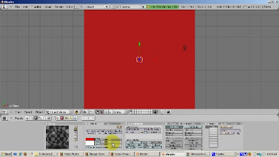
Position the camera directly at the plane with View - Align View - Align Active Camera to View.
Go to Front View (Num1). Press the Home key to see all the objects, particularly, the camera. Duplicate the plane (Shift-D). Move the plane upwards, in the Z direction (press the G key and then the Z key), so that it is behind the camera. The duplicated plane has Ray Mirror on as well.
Go to the Scene buttons (F10). Make sure the Ray button is turned on, so that Ray Tracing is enabled.
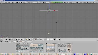
Center the 3D cursor by pressing Shift-C. Add the monkey (Space - Add - Mesh - Monkey). Add a new material by pressing F5 (Shaders) and clicking the Add New button. Make Suzanne green (R=0, G=1, B=0). Move the monkey 1 blender unit to the right and up a bit. Go to Edit buttons (F9). Press the Set Smooth button. Add a Subsurf Level 2, Render Level 3.
Make sure you are in Object Mode. If not, press the tab key. Add a UV Sphere (Space - Add - Mesh - UVSphere). Give the UV Sphere a blue color by going to the Shaders panel (F5), adding a new material (Add New button) and setting R=0, G=0, and B=1. Move the UV Sphere 2 blender units to the left and up a bit, off the floor of the plane. Press F9 to go to the Edit buttons. Click the Set Smooth button to smooth out the UV Sphere.
Press F12 to render. The red mirror should show the mirroring of both the monkey and the UV Sphere, as the light bounces off the bottom mirror, sees the monkey and the UV Sphere, and then the objects are mirrored off the top mirror. The shadow obscures somewhat the mirrored effect.
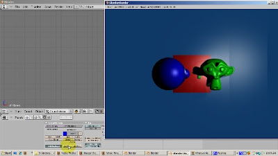
Let's turn off shadows. Go to the Scene buttons (F10) and click off Shadow. Press F12 to render. Now you get the effect of both the top mirror and the bottom mirror.
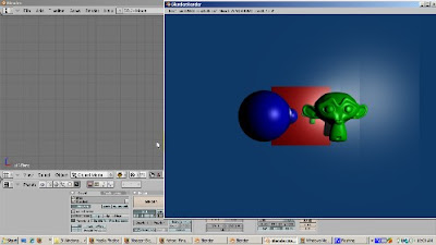
The mirror effect can be combined with the color effect. Select either mirror plane (Right click). Press F5 to access the Shaders buttons. In the Ray Mirror group, turn Ray Mirror to 0. Press F12 to render. There is no mirror effect. The monkey and the UV Sphere both render, and the plane is red.
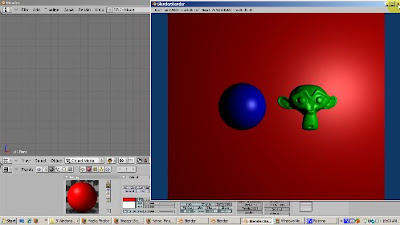
Now set Ray Mirror to .5, so we get half mirror and half color. Press F12 to render. Now the red base color shows through, but the mirror effect shows through as well. You can play with Ray Mirror to get the combination you like.
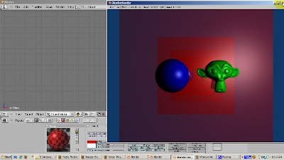
The mirror color can also play a role. Turn Ray Mirror back to 1 so we get the full ray mirror effect. Now let's set the mirror color to yellow. Select the Mirror color rectangle, and change it to Yellow (R=1, G=1, B=0). Press F12 to render. We get a really interestng result. The yellow mirror color mixes with the material's color. The monkey is green. Yellow already has green. So the mirrored monkey remains green. However, the sphere is blue. The mirror color, yellow, has no blue, so the mirrored UV sphere is yellow. By the way, there's also a blending with the sky color, which is also mirrored, which accounts for the color variation outside the mirror boundary.
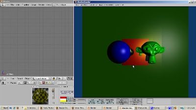
The Depth setting controls how many times the mirror effect bouncing is produced. Let's crank up the depth to 5 and press F12 to render. There are now more mirrored monkeys and UV Spheres.
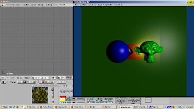
The Fresnel setting produces another interesting effect, mixing the mirror color, and the mirror's diffuse color. Let's crank Fresnel to 1.5 and render.
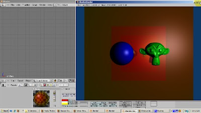
The Glossiness setting affects the blurriness of the reflection. The default of 100% glossiness produces a crisp reflection. A little bit of reduction goes a long way in increasing the realism of the render. Set glossiness to .9 (90%) and you'll get an effect that simulates a bit of dirt in the mirror.
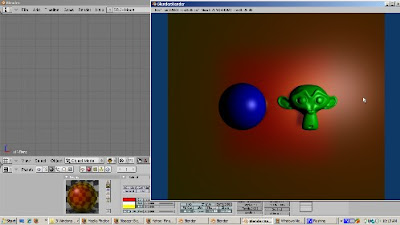
There's more. How about turning on Ray Mirror for the monkey and the UV Sphere. Select the monkey. Go to the Shading buttons (F5). Click the Ray Mirror button. Turn RayMir to 1. Then select the UVSphere, go to the shading buttons, and turn on Ray Mirror, setting it to 1. Press F12 to render. How about changing the mirror's shape? Subdivide the plane, rotate a few vertices, and render. I'll leave that to you.
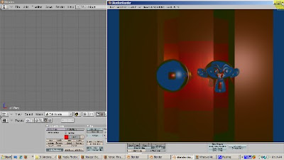
As you can see, there are a lot of neat effects you can achieve with Ray Mirror. I hope you have the basis for experimenting more and getting the effect you desire. Happy Blendering!
Ray tracing casts simulated rays of light on the scene and is on by default in Blender 2.49. Ray tracing gives the most realistic light properties in Blender, but the renders take the longest. That is why all of my renders in this video will be time lapsed. Don't expect the same rendering times as you see in this video, unless you work for Pixar or the Defense Department. For many animation and game engine applications, ray tracing rendering times are unacceptably slow. In other videos, we will discover alternatives, such as Z buffering, for which response times are more acceptable. However, the effects won't be as realistic as with ray mirror. In this video, we will be looking at a special type of ray tracing effect, ray mirror, which creates mirror reflections.
When a ray of light hits the surface of an object, one of three things can happen. The light can be absorbed by the object, the light can pass through the object (if the object has some transparency), or the light can be reflected back, which is what happens with a mirror. In reality, most objects have a combination of absorption, transparency, and reflective properties. Think of a blue light bulb. The light bulb looks blue because some of the light is absorbed by the material, glass or otherwise, to make it look blue. Perhaps you can see part of the inside of the light bulb, say if it is not frosted, such as the filament. That's because the light bulb has some transparent properties. Finally, if you can see part of the background through the light bulb, that's because of its mirror like, reflective properties. Ray Mirror controls this last property.
To show how Ray Mirror works, start up Blender and delete the default cube. Select the cube, press the Delete key and press Enter to confirm. Make sure you are in Top View by pressing Num7. Add a plane (Space - Add - Mesh - Plane). Scale the plane 5 times (S - 5 - Enter). The plane is going to act as a mirror. To make this happen, with the full Ray Mirror effect, press the Shading buttons (F5) and use the default material (Material). Click the Mirror Trans tab, then click the Ray Mirror button, and turn RayMir to 1. RayMir is a slider which goes from 0 to 1, representing 0% to 100% as a decimal number. Give the plane a red color (R=1, G=0, B=0).

Position the camera directly at the plane with View - Align View - Align Active Camera to View.
Go to Front View (Num1). Press the Home key to see all the objects, particularly, the camera. Duplicate the plane (Shift-D). Move the plane upwards, in the Z direction (press the G key and then the Z key), so that it is behind the camera. The duplicated plane has Ray Mirror on as well.
Go to the Scene buttons (F10). Make sure the Ray button is turned on, so that Ray Tracing is enabled.

Center the 3D cursor by pressing Shift-C. Add the monkey (Space - Add - Mesh - Monkey). Add a new material by pressing F5 (Shaders) and clicking the Add New button. Make Suzanne green (R=0, G=1, B=0). Move the monkey 1 blender unit to the right and up a bit. Go to Edit buttons (F9). Press the Set Smooth button. Add a Subsurf Level 2, Render Level 3.
Make sure you are in Object Mode. If not, press the tab key. Add a UV Sphere (Space - Add - Mesh - UVSphere). Give the UV Sphere a blue color by going to the Shaders panel (F5), adding a new material (Add New button) and setting R=0, G=0, and B=1. Move the UV Sphere 2 blender units to the left and up a bit, off the floor of the plane. Press F9 to go to the Edit buttons. Click the Set Smooth button to smooth out the UV Sphere.
Press F12 to render. The red mirror should show the mirroring of both the monkey and the UV Sphere, as the light bounces off the bottom mirror, sees the monkey and the UV Sphere, and then the objects are mirrored off the top mirror. The shadow obscures somewhat the mirrored effect.

Let's turn off shadows. Go to the Scene buttons (F10) and click off Shadow. Press F12 to render. Now you get the effect of both the top mirror and the bottom mirror.

The mirror effect can be combined with the color effect. Select either mirror plane (Right click). Press F5 to access the Shaders buttons. In the Ray Mirror group, turn Ray Mirror to 0. Press F12 to render. There is no mirror effect. The monkey and the UV Sphere both render, and the plane is red.

Now set Ray Mirror to .5, so we get half mirror and half color. Press F12 to render. Now the red base color shows through, but the mirror effect shows through as well. You can play with Ray Mirror to get the combination you like.

The mirror color can also play a role. Turn Ray Mirror back to 1 so we get the full ray mirror effect. Now let's set the mirror color to yellow. Select the Mirror color rectangle, and change it to Yellow (R=1, G=1, B=0). Press F12 to render. We get a really interestng result. The yellow mirror color mixes with the material's color. The monkey is green. Yellow already has green. So the mirrored monkey remains green. However, the sphere is blue. The mirror color, yellow, has no blue, so the mirrored UV sphere is yellow. By the way, there's also a blending with the sky color, which is also mirrored, which accounts for the color variation outside the mirror boundary.

The Depth setting controls how many times the mirror effect bouncing is produced. Let's crank up the depth to 5 and press F12 to render. There are now more mirrored monkeys and UV Spheres.

The Fresnel setting produces another interesting effect, mixing the mirror color, and the mirror's diffuse color. Let's crank Fresnel to 1.5 and render.

The Glossiness setting affects the blurriness of the reflection. The default of 100% glossiness produces a crisp reflection. A little bit of reduction goes a long way in increasing the realism of the render. Set glossiness to .9 (90%) and you'll get an effect that simulates a bit of dirt in the mirror.

There's more. How about turning on Ray Mirror for the monkey and the UV Sphere. Select the monkey. Go to the Shading buttons (F5). Click the Ray Mirror button. Turn RayMir to 1. Then select the UVSphere, go to the shading buttons, and turn on Ray Mirror, setting it to 1. Press F12 to render. How about changing the mirror's shape? Subdivide the plane, rotate a few vertices, and render. I'll leave that to you.

As you can see, there are a lot of neat effects you can achieve with Ray Mirror. I hope you have the basis for experimenting more and getting the effect you desire. Happy Blendering!
Tuesday, December 8, 2009
Multiple Materials
Join my Blender 3D forum, where you can network with other Blender friends and get your Blender 3D questions answered.
Many times you will be assigning one material to an entire object. However, there are situations where you want to assign different parts of an object to their own material. The assignment can get kind of tricky. In this demo, we will make each face of a cube have a different colored material. You can then extend this to customize each material, such as changing its opacity or transparency, on each face. You can also add separate textures to each material. This tutorial shows you how to do the first step: creating a separate material for each face of a cube.
Steps:
1) We'll start with the default 2.49b scene and use the default cube. Press Tab to go to Edit mode. Go to Face Select mode (Control - Tab - 3 or the triangle icon. Press A to deselect all faces. Rotate the cube on its side, to make selecting a face easier. Press Z to go to wireframe mode.
Materials are assigned per face. Each face can have only 1 material ID. New materials are given the next material ID, 2 for the second one, 3 for the third one, and so on. A set of buttons in Edit (F9( assigns multiple material IDs. By default, when you Add New material, all faces have a Material ID 1. Press F5 for the shading buttons. There's an indicator (1 Mat 1) that shows how many materials are on the object (1), and which one we're working on (1).
2) Create 5 new materials. By default, each face of the cube has a material, called Material, assigned to it. The Material button group shows that there is 1 material assigned to the cube. Press F9 to get to the Editing buttons. Press the New key 5 times. Now there are 6 materials, with the names Material, Material.001, Material.002, all the way to Material.005.
3) Assign the faces to their respective materials:
Go to F9 (Editing buttons). Assign the faces as follows:
Select the top face. Set its material to Material (ID = 1). Click Assign.
Select the bottom face. Set its material to Material.001 (ID = 2). Click Assign.
Select the left face. Set its material to Material.002 (ID = 3) Click Assign.
Select the right face. Set its material to Material.003 (ID=4). Click Assign.
Select the front face. Set its material to Material.004 (ID = 5). Click Assign.
Select the back face. Set its material to Material.005 (ID=6). Click Assign.
You can verify which material is associated with which face. Press the A key to deselect all faces. Select a material, say Material.004. Click the Select button and you should see that the material is assigned to the top face. You can also do the opposite. Press A to deselect all faces. Click the bottom face. Click the question mark icon. You should see that Material.001, with material ID 2, is assigned.
4) Click F5 to go to the Shading buttons. We want our materials to have meaningful names so we can identify them easily. Assign the following colors:
Material: Red (R=1, G=0, B=0). Press Autoname to have Blender create a meaningful name (Red).
Material.001: Green (R=0, G=1, B=0). Press Autoname. Blender calls this LightGreen.
Material.002: Blue (R=0, G=0, B=1). Press Autoname. Blender calls this LightBlue.
Material.003: Yellow (R=1, G=1, B=0). Press Autoname. Blender calls this material Yellow.
Material.004: Magenta (R=1, G=0, B=1). Press Autoname. Blender calls this material Magenta.
Material.005: Cyan (R=0, G=1, B=1). Press Autoname. Blender calls this material Cyan.
To view our result, press Tab to go into Object mode. Then go into Shaded mode. Rotate the cube. Press F12 to render.
You can further refine this by changing the characteristics of a material by playing with settings such as Ray Mirror, Alpha, Ray Transparency, the render pipeline, and so on. You can produce some interesting effects. Happy Blendering.
Many times you will be assigning one material to an entire object. However, there are situations where you want to assign different parts of an object to their own material. The assignment can get kind of tricky. In this demo, we will make each face of a cube have a different colored material. You can then extend this to customize each material, such as changing its opacity or transparency, on each face. You can also add separate textures to each material. This tutorial shows you how to do the first step: creating a separate material for each face of a cube.
Steps:
1) We'll start with the default 2.49b scene and use the default cube. Press Tab to go to Edit mode. Go to Face Select mode (Control - Tab - 3 or the triangle icon. Press A to deselect all faces. Rotate the cube on its side, to make selecting a face easier. Press Z to go to wireframe mode.
Materials are assigned per face. Each face can have only 1 material ID. New materials are given the next material ID, 2 for the second one, 3 for the third one, and so on. A set of buttons in Edit (F9( assigns multiple material IDs. By default, when you Add New material, all faces have a Material ID 1. Press F5 for the shading buttons. There's an indicator (1 Mat 1) that shows how many materials are on the object (1), and which one we're working on (1).
2) Create 5 new materials. By default, each face of the cube has a material, called Material, assigned to it. The Material button group shows that there is 1 material assigned to the cube. Press F9 to get to the Editing buttons. Press the New key 5 times. Now there are 6 materials, with the names Material, Material.001, Material.002, all the way to Material.005.
3) Assign the faces to their respective materials:
Go to F9 (Editing buttons). Assign the faces as follows:
Select the top face. Set its material to Material (ID = 1). Click Assign.
Select the bottom face. Set its material to Material.001 (ID = 2). Click Assign.
Select the left face. Set its material to Material.002 (ID = 3) Click Assign.
Select the right face. Set its material to Material.003 (ID=4). Click Assign.
Select the front face. Set its material to Material.004 (ID = 5). Click Assign.
Select the back face. Set its material to Material.005 (ID=6). Click Assign.
You can verify which material is associated with which face. Press the A key to deselect all faces. Select a material, say Material.004. Click the Select button and you should see that the material is assigned to the top face. You can also do the opposite. Press A to deselect all faces. Click the bottom face. Click the question mark icon. You should see that Material.001, with material ID 2, is assigned.
4) Click F5 to go to the Shading buttons. We want our materials to have meaningful names so we can identify them easily. Assign the following colors:
Material: Red (R=1, G=0, B=0). Press Autoname to have Blender create a meaningful name (Red).
Material.001: Green (R=0, G=1, B=0). Press Autoname. Blender calls this LightGreen.
Material.002: Blue (R=0, G=0, B=1). Press Autoname. Blender calls this LightBlue.
Material.003: Yellow (R=1, G=1, B=0). Press Autoname. Blender calls this material Yellow.
Material.004: Magenta (R=1, G=0, B=1). Press Autoname. Blender calls this material Magenta.
Material.005: Cyan (R=0, G=1, B=1). Press Autoname. Blender calls this material Cyan.
To view our result, press Tab to go into Object mode. Then go into Shaded mode. Rotate the cube. Press F12 to render.
You can further refine this by changing the characteristics of a material by playing with settings such as Ray Mirror, Alpha, Ray Transparency, the render pipeline, and so on. You can produce some interesting effects. Happy Blendering.
Sunday, December 6, 2009
Rip Tool
Join my Blender 3D forum, where you can network with other Blender friends and get your Blender 3D questions answered.
The Rip tool lets you tear out a hole, such as a mouth or an eye socket if you're modeling a face, in your mesh. You can use the Rip Tool in either vertex select or edge select mode. The Rip Tool does not work in Face Select Mode. You can also use the Rip tool to do split apart a mesh, for example, splitting a sphere into two halves. You can create faces to join the parts of the mesh that you have ripped. The goal of this tutorial is to make you comfortable both ripping a mesh apart to create holes where you want them, and to join mesh parts together again.
We'll start with the default Blender 2.49b scene. Delete the default cube (press the Delete key and press Enter to confirm). Add a plane (Space - Add - Mesh - Plane). The plane is in Object mmode. Scale the plane to 4 times its original size (S - 4 - Enter). Get rid of the 3D Transform Manipulator to make the demonstration of the Rip Tool easier to follow.
Press Tab to go into Edit mode. Press the Edit buttons (F9) and click the Subdivide button 3 times. Press the A key to deselect all vertices.
Look at the indicators for vertices, edges, and faces. Right now, the plane has 81 vertices, 144 edges, and 64 faces. The zeroes show that nothing is selected.
Make sure you are in Vertex Select Mode (Control - Tab - 1) or the Vertex Select icon. Position the 3D cursor below and to the right of the vertex you want to select. Select the vertex, then press the V key, grabbing the vertex to the right. A hole is created to the right of the vertex. Look at the indicators for vertices, edges, and faces. Before the plane had 81 vertices, of which none were selected. Now, the plane has 82 vertices, and one is selected.
This gives a clue as to what the Rip tool actually does. It creates a duplicate vertex at the same spot as the selected vertex, connected to the vertices as the copied vertex. When the mesh is ripped, that vertex drags the adjacent edges with it. The 3D cursor position determines the direction of the rip.
Press Alt-U, which brings up the Undo History. Click on Select to undo the rip. Now we're back to having the vertex selected, with 81 vertices altgether. Move the cursor above and to the left of the selected vertex. You can constrain the rip to an axis. To do that, press the V key, and then the Y key to constrain the rip to the Y axis. Press Enter to confirm. So you can see that the direction of the rip depends on the position of the 3D cursor at the time that you press the V key. The rip is along the edge that is closest to the selected vertex.
Press the A key to deselect the vertex. Go to another part of the plane, and select a vertex. Then Shift select (Shift - Right Click) the vertex immediately to the right of it. Position the 3D cursor above and in the middle of the selected vertices. Press the V key. You now get a bigger rip, a trapezoid, with 2 vertices on top and 4 vertices on the bottom. So a rip with N selected vertices produces a ripped polygon with N vertices in the ripped direction and N+2 vertices in the original direction.
If you start the Rip and then immediately decide not to continue, the new vertices still remain. To illustrate this, select a vertex, press the V key, and then press Esc. The vertex created by the Rip tool is still there. You can rip the mesh now even though you pressed Esc. Press the G key and move the vertex and the mesh is ripped. Press Enter to confirm.
Press the A key to deselect all vertices. Suppose you want to patch up the hole that you created. The solution is to select the vertices for the new face (3 or 4) and press the F key. To illustrate this, select the 4 vertices that form the square of the hole created from 2 selected vertices. Press the F key. A face is created.
Press the A key to deselect all vertices. Now we'll create triangular faces for the remaining two holes. Select the 3 vertices forming the left triangle, and press F. Press the A key to deselect everything. Select the 3 vertices forming the right triangle, and press F. The hole is now repaired. Press the A key to deselect.
Ripping via an edge loop is a great way to split a mesh. Select an Edge Loop by positioning the 3D cursor on an edge and pressing Alt-Right Click. Then press the V key and scroll down. Press Enter to confirm. You have now split the mesh along the edge loop.
Rip works in edge mode as well. Go into Edge mode, by either selecting the Edge icon or pressing Control - Tab - 2. Position the 3D cursor above an edge to select. Select the edge (Right Click on an edge). Press the V key. The rip works just like selecting two adjacent vertices, which is, of course, what constitutes an edge.
Press the A key to deselect everything. You rip on two edges along the same loop. Select an unselected edge. Then Shift Select (right click while holding the Shift key) to select the edge next to it. Press the V key. The rip works in the trapezoidal fashion you would expect.
Rip works on other meshes as well. Let's look at a UV Sphere. Press tab to go to object mode. Click the second square to go to Level 2, so we have a blank 3D viewport. Add a UV Sphere (Space - Add - Mesh -UVSphere), accepting the default of 32 rings and 32 segments. Press Z to go into wireframe mode. Scale the UVSphere 3 times (S - 3 - Enter). Press Tab to go into Edit mode. Go into Edge select mode (Control - Tab - 2). Press the A key to deselect everything.
Press Num 1 key to go to front view. Position the cursor on an edge and press Alt-Right Click to select an edge loop. Position the 3D cursor below the selected loop. Press the V key. Move the selected edge loop down. Behold, you have split the UV Sphere. Press Z to go into solid mode so you can see.
Ycu can also rip and scale at the same time. Select another edge loop (Alt- Right Click) for splitting the UV Sphere. Position the 3D cursor below the loop. Press the V key, then the Z key to constrain along the Z axis, drag the edge down. Press Enter. Then press the S key to scale the loop.
I hope this gives you a good idea of the Rip tool, which is very handy for creating holes in a mesh. Happy Blendering!
The Rip tool lets you tear out a hole, such as a mouth or an eye socket if you're modeling a face, in your mesh. You can use the Rip Tool in either vertex select or edge select mode. The Rip Tool does not work in Face Select Mode. You can also use the Rip tool to do split apart a mesh, for example, splitting a sphere into two halves. You can create faces to join the parts of the mesh that you have ripped. The goal of this tutorial is to make you comfortable both ripping a mesh apart to create holes where you want them, and to join mesh parts together again.
We'll start with the default Blender 2.49b scene. Delete the default cube (press the Delete key and press Enter to confirm). Add a plane (Space - Add - Mesh - Plane). The plane is in Object mmode. Scale the plane to 4 times its original size (S - 4 - Enter). Get rid of the 3D Transform Manipulator to make the demonstration of the Rip Tool easier to follow.
Press Tab to go into Edit mode. Press the Edit buttons (F9) and click the Subdivide button 3 times. Press the A key to deselect all vertices.
Look at the indicators for vertices, edges, and faces. Right now, the plane has 81 vertices, 144 edges, and 64 faces. The zeroes show that nothing is selected.
Make sure you are in Vertex Select Mode (Control - Tab - 1) or the Vertex Select icon. Position the 3D cursor below and to the right of the vertex you want to select. Select the vertex, then press the V key, grabbing the vertex to the right. A hole is created to the right of the vertex. Look at the indicators for vertices, edges, and faces. Before the plane had 81 vertices, of which none were selected. Now, the plane has 82 vertices, and one is selected.
This gives a clue as to what the Rip tool actually does. It creates a duplicate vertex at the same spot as the selected vertex, connected to the vertices as the copied vertex. When the mesh is ripped, that vertex drags the adjacent edges with it. The 3D cursor position determines the direction of the rip.
Press Alt-U, which brings up the Undo History. Click on Select to undo the rip. Now we're back to having the vertex selected, with 81 vertices altgether. Move the cursor above and to the left of the selected vertex. You can constrain the rip to an axis. To do that, press the V key, and then the Y key to constrain the rip to the Y axis. Press Enter to confirm. So you can see that the direction of the rip depends on the position of the 3D cursor at the time that you press the V key. The rip is along the edge that is closest to the selected vertex.
Press the A key to deselect the vertex. Go to another part of the plane, and select a vertex. Then Shift select (Shift - Right Click) the vertex immediately to the right of it. Position the 3D cursor above and in the middle of the selected vertices. Press the V key. You now get a bigger rip, a trapezoid, with 2 vertices on top and 4 vertices on the bottom. So a rip with N selected vertices produces a ripped polygon with N vertices in the ripped direction and N+2 vertices in the original direction.
If you start the Rip and then immediately decide not to continue, the new vertices still remain. To illustrate this, select a vertex, press the V key, and then press Esc. The vertex created by the Rip tool is still there. You can rip the mesh now even though you pressed Esc. Press the G key and move the vertex and the mesh is ripped. Press Enter to confirm.
Press the A key to deselect all vertices. Suppose you want to patch up the hole that you created. The solution is to select the vertices for the new face (3 or 4) and press the F key. To illustrate this, select the 4 vertices that form the square of the hole created from 2 selected vertices. Press the F key. A face is created.
Press the A key to deselect all vertices. Now we'll create triangular faces for the remaining two holes. Select the 3 vertices forming the left triangle, and press F. Press the A key to deselect everything. Select the 3 vertices forming the right triangle, and press F. The hole is now repaired. Press the A key to deselect.
Ripping via an edge loop is a great way to split a mesh. Select an Edge Loop by positioning the 3D cursor on an edge and pressing Alt-Right Click. Then press the V key and scroll down. Press Enter to confirm. You have now split the mesh along the edge loop.
Rip works in edge mode as well. Go into Edge mode, by either selecting the Edge icon or pressing Control - Tab - 2. Position the 3D cursor above an edge to select. Select the edge (Right Click on an edge). Press the V key. The rip works just like selecting two adjacent vertices, which is, of course, what constitutes an edge.
Press the A key to deselect everything. You rip on two edges along the same loop. Select an unselected edge. Then Shift Select (right click while holding the Shift key) to select the edge next to it. Press the V key. The rip works in the trapezoidal fashion you would expect.
Rip works on other meshes as well. Let's look at a UV Sphere. Press tab to go to object mode. Click the second square to go to Level 2, so we have a blank 3D viewport. Add a UV Sphere (Space - Add - Mesh -UVSphere), accepting the default of 32 rings and 32 segments. Press Z to go into wireframe mode. Scale the UVSphere 3 times (S - 3 - Enter). Press Tab to go into Edit mode. Go into Edge select mode (Control - Tab - 2). Press the A key to deselect everything.
Press Num 1 key to go to front view. Position the cursor on an edge and press Alt-Right Click to select an edge loop. Position the 3D cursor below the selected loop. Press the V key. Move the selected edge loop down. Behold, you have split the UV Sphere. Press Z to go into solid mode so you can see.
Ycu can also rip and scale at the same time. Select another edge loop (Alt- Right Click) for splitting the UV Sphere. Position the 3D cursor below the loop. Press the V key, then the Z key to constrain along the Z axis, drag the edge down. Press Enter. Then press the S key to scale the loop.
I hope this gives you a good idea of the Rip tool, which is very handy for creating holes in a mesh. Happy Blendering!
Monday, November 30, 2009
2.49b Edge and Face Loops
Join my Blender 3D forum, where you can network with other Blender friends and get your Blender 3D questions answered.
You can select the subcomponents of a mesh by either right clicking, or shift right click, or the B key to box select, or the B key twice to form a circle selection, or alt left click for lasso select. There's another way to select parts of a mesh, which is by selecting a loop of vertices, edges, or faces. Also, adding loops is a great way to add detail to your mesh. Instead of subdividing a mesh, which adds a lot of extra geometry when it's not needed, adding loops only in the area where you want detail will create a cleaner mesh with fewer edges, vertices, and faces. The aim of this tutorial is to demonstrate how to use loops both to select parts of your mesh and to add details to it.
Selecting By Loops
We'll work with the default cube. It's selected and in Object Mode. Go to the Edit buttons (F9) and press Tab to go into Edit mode. Press the Subdivide button, in the Mesh Tools panel, three times. Rotate the view, using either the middle mouse button or alt-Left Mouse Button if you enabled Emulate 3 Button Mouse in the Preferences window. We're in Vertex Select mode. Position the 3D Cursor at one of the corner vertices. Hold the Alt key down and press the Right Mouse button. Doing that, selects not just the vertex (which is what Right Mouse button does just by itself), but the entire edge that the vertex belongs to.
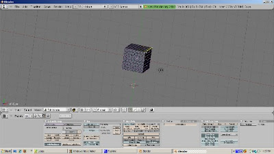
Press the A key to deselect the vertices.
Now hold the Alt key down and select a vertex that is not on the outside edge but instead is inside the cube. This time, an entire loop of edges is selected - the loop that that vertex belongs to. The loop could be horizontal or vertical.
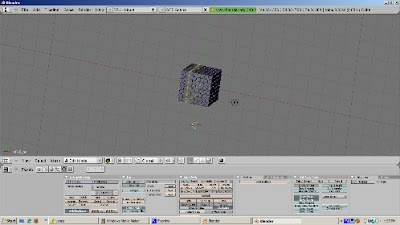
Press the A key to deselect everything. You can also select the perpendicular range of faces to which the edge belongs by holding both the Control key and the Alt key at the same time. To illustrate, press the Control key and the Alt key at the same time, and select a vertex. What is selected is the faces on the edge perpendicular to the vertex.
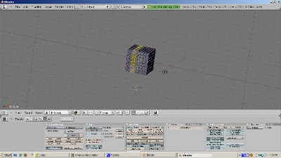
You can add to the loop selection, in effect selecting multiple loops, by holding the Shift Key down as well as the Alt Key. Hold the both the Alt and Shift keys and select an unselected vertex. Now you have selected two loops. If the loop includes all the vertices that form a face, those faces will be selected as well.
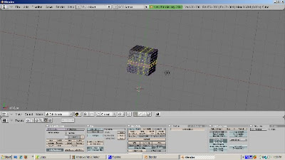
If you feel particularly ambidexterous, try holding the Control, Alt, and Shift keys down at the same time, and select another vertex. You then add to the faces selected before.
Loop selection works in edge select mode as well. Holding the Alt key and then clicking the right mouse button selects the loop to which the edge belongs to. Press the A key to deselect everything. If we go into Face Select mode, we see that loops of faces can also be selected this way. Hold the Alt kay, and with the 3D cursor on a face, press the right mouse button to select a face loop. Hold both the Shift key and the Alt key, select an unselected face with the right mouse button, and the loop in which the selected face belongs is added to the selection.
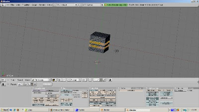
Selecting loops of vertices, edges, or faces, can make the selection process much more precise than box selection or selection of individual vertices, edges, or faces.
Creating Loops On A Cube
You can add edge loops with the Loop Subdivide tool (Control-R). To illustrate, position the cursor on an edge of the cube, and press Control-R. A magenta square shows where the new loop will be cut. However, you actually have more control over where the loop cut will occur. Press Enter.
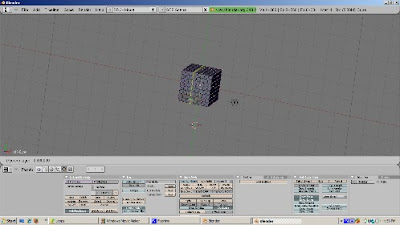
Now you see both the proposed new loop, and a green line, which is the edge along which you can slide this loop. This is called "edge slide mode". A green line, showing the edge along which the loop can be cut, displays. You can scroll the edge up and down along the green line. Press Enter when you get to the position of the new edge that you want.
You can create more than one edge loop at a time. Position the cursor at an edge along where you would like to cut and press Control-R. Now, instead of pressing Enter, press the + key on the numeric keypad. This adds a loop cut, allowing you to create two loop cuts at a time. You can press the + key on the numeric keypad to add another loop cut, or you can press the - key on the numeric keypad to subtract 1 loop cut. Then press Enter. Edge Slide mode does not work when you create more than one edge loop. Instead, the loops are split evenly along the edge.
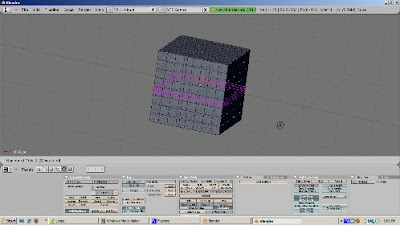
Creating Loops On A UV Sphere
Let's start with the default scene by selecting Load Factory Settings from the menu. Delete the default cube (press the Delete key, then press OK to accept the delete). Add a UV Sphere (Space - Add - Mesh - UVSphere), accepting the default settings of 32 rings and 32 segments. Press Tab to go into Edit Mode. Press A to deselect everything. Press Control-R. You can create edge loops either based on rings (going left and right) or segments (going up and down). Lets add an edge loop based on a ring. Press Control-R, selecting a horizontal edge loop to create. This selection works the same way as for a cube. Press Enter, to go into Edge Slide mode. Position the loop where you want and press Enter. However, for a ring, the edge loop only is created on half the UV Sphere. Press Control-R, then Enter. Slide the edge where you want it. Then press Enter. Rotate the UV Sphere and you will see the result. To get the edge loop to go around the UV Sphere, you will need to create the corresponding edge loop on the other side of the sphere.
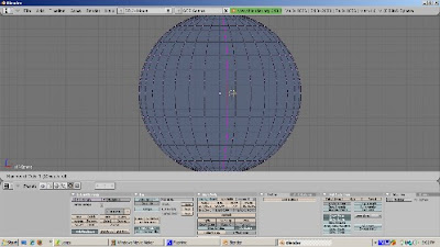
You can add more than one loop cut using the + key on the numeric keypad, and subtract using the - key on the numeric keypad, as with the cube.
Control - Alt - Right Click and Shift - Control- Alt - Right Click work the same way on a UV Sphere as on a cube. You can create a loop of faces perpendicular to the edge you select with Control - Alt Right Click, and extend the selection if you somehow manage to hold Shift, Control, Alt, and Right Click while the 3D cursor is on an unselected face.
As you can see, selecting and adding loops can make your mesh modeling more precise when you're adding detail. These techniques work on any mesh, not just the cube or UV Sphere. Try them with a torus, or with Suzanne, and you should get the hang of loop selection and addition quickly. Happy Blendering!
You can select the subcomponents of a mesh by either right clicking, or shift right click, or the B key to box select, or the B key twice to form a circle selection, or alt left click for lasso select. There's another way to select parts of a mesh, which is by selecting a loop of vertices, edges, or faces. Also, adding loops is a great way to add detail to your mesh. Instead of subdividing a mesh, which adds a lot of extra geometry when it's not needed, adding loops only in the area where you want detail will create a cleaner mesh with fewer edges, vertices, and faces. The aim of this tutorial is to demonstrate how to use loops both to select parts of your mesh and to add details to it.
Selecting By Loops
We'll work with the default cube. It's selected and in Object Mode. Go to the Edit buttons (F9) and press Tab to go into Edit mode. Press the Subdivide button, in the Mesh Tools panel, three times. Rotate the view, using either the middle mouse button or alt-Left Mouse Button if you enabled Emulate 3 Button Mouse in the Preferences window. We're in Vertex Select mode. Position the 3D Cursor at one of the corner vertices. Hold the Alt key down and press the Right Mouse button. Doing that, selects not just the vertex (which is what Right Mouse button does just by itself), but the entire edge that the vertex belongs to.

Press the A key to deselect the vertices.
Now hold the Alt key down and select a vertex that is not on the outside edge but instead is inside the cube. This time, an entire loop of edges is selected - the loop that that vertex belongs to. The loop could be horizontal or vertical.

Press the A key to deselect everything. You can also select the perpendicular range of faces to which the edge belongs by holding both the Control key and the Alt key at the same time. To illustrate, press the Control key and the Alt key at the same time, and select a vertex. What is selected is the faces on the edge perpendicular to the vertex.

You can add to the loop selection, in effect selecting multiple loops, by holding the Shift Key down as well as the Alt Key. Hold the both the Alt and Shift keys and select an unselected vertex. Now you have selected two loops. If the loop includes all the vertices that form a face, those faces will be selected as well.

If you feel particularly ambidexterous, try holding the Control, Alt, and Shift keys down at the same time, and select another vertex. You then add to the faces selected before.
Loop selection works in edge select mode as well. Holding the Alt key and then clicking the right mouse button selects the loop to which the edge belongs to. Press the A key to deselect everything. If we go into Face Select mode, we see that loops of faces can also be selected this way. Hold the Alt kay, and with the 3D cursor on a face, press the right mouse button to select a face loop. Hold both the Shift key and the Alt key, select an unselected face with the right mouse button, and the loop in which the selected face belongs is added to the selection.

Selecting loops of vertices, edges, or faces, can make the selection process much more precise than box selection or selection of individual vertices, edges, or faces.
Creating Loops On A Cube
You can add edge loops with the Loop Subdivide tool (Control-R). To illustrate, position the cursor on an edge of the cube, and press Control-R. A magenta square shows where the new loop will be cut. However, you actually have more control over where the loop cut will occur. Press Enter.

Now you see both the proposed new loop, and a green line, which is the edge along which you can slide this loop. This is called "edge slide mode". A green line, showing the edge along which the loop can be cut, displays. You can scroll the edge up and down along the green line. Press Enter when you get to the position of the new edge that you want.
You can create more than one edge loop at a time. Position the cursor at an edge along where you would like to cut and press Control-R. Now, instead of pressing Enter, press the + key on the numeric keypad. This adds a loop cut, allowing you to create two loop cuts at a time. You can press the + key on the numeric keypad to add another loop cut, or you can press the - key on the numeric keypad to subtract 1 loop cut. Then press Enter. Edge Slide mode does not work when you create more than one edge loop. Instead, the loops are split evenly along the edge.

Creating Loops On A UV Sphere
Let's start with the default scene by selecting Load Factory Settings from the menu. Delete the default cube (press the Delete key, then press OK to accept the delete). Add a UV Sphere (Space - Add - Mesh - UVSphere), accepting the default settings of 32 rings and 32 segments. Press Tab to go into Edit Mode. Press A to deselect everything. Press Control-R. You can create edge loops either based on rings (going left and right) or segments (going up and down). Lets add an edge loop based on a ring. Press Control-R, selecting a horizontal edge loop to create. This selection works the same way as for a cube. Press Enter, to go into Edge Slide mode. Position the loop where you want and press Enter. However, for a ring, the edge loop only is created on half the UV Sphere. Press Control-R, then Enter. Slide the edge where you want it. Then press Enter. Rotate the UV Sphere and you will see the result. To get the edge loop to go around the UV Sphere, you will need to create the corresponding edge loop on the other side of the sphere.

You can add more than one loop cut using the + key on the numeric keypad, and subtract using the - key on the numeric keypad, as with the cube.
Control - Alt - Right Click and Shift - Control- Alt - Right Click work the same way on a UV Sphere as on a cube. You can create a loop of faces perpendicular to the edge you select with Control - Alt Right Click, and extend the selection if you somehow manage to hold Shift, Control, Alt, and Right Click while the 3D cursor is on an unselected face.
As you can see, selecting and adding loops can make your mesh modeling more precise when you're adding detail. These techniques work on any mesh, not just the cube or UV Sphere. Try them with a torus, or with Suzanne, and you should get the hang of loop selection and addition quickly. Happy Blendering!
Friday, November 27, 2009
Incredible Machines Book
There's an exciting book coming out soon, called Blender 3D 2.49 Incredible Machines. The video shows an example of what the reader will be able to create, using Blender 3D to model the entire scene and setup all lights and materials with LuxRender. In LuxRender we will use an incredible feature called Light Groups to control all lights on the scene, with the image still rendering. Notice that we can turn on and off all lights and see the result in real time, and there are lots of other possible adjustments like the temperature of light and much more.
The video is based on the book's third project. It was created by the author, Allan Brito. Allan is an active member of the Blender development community. He's a Brazilian architect who specializes in information visualization. This is his 3rd Blender book.
This book will show you how to use Blender 3D for mechanical modeling and product visualization. Through the pages of the book, you will find a step-by-step guide to create three different projects: a fantasy weapon, a spacecraft, and a giant robot. Even though these machines are not realistic, you will be able to build your own sensible and incredible machines with the techniques that you will learn in this book along with the exercises and examples.
If you want to model machines and want to understand in depth industrial uses of Blender, this sounds like a book to examine closely.
Subscribe to:
Posts (Atom)