Monday, November 30, 2009

2.49b Edge and Face Loops

Join my Blender 3D forum, where you can network with other Blender friends and get your Blender 3D questions answered.


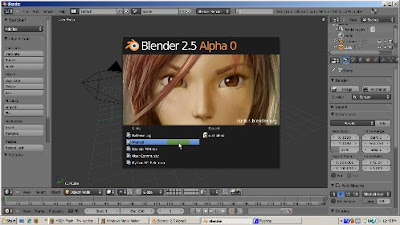
You can select the subcomponents of a mesh by either right clicking, or shift right click, or the B key to box select, or the B key twice to form a circle selection, or alt left click for lasso select. There's another way to select parts of a mesh, which is by selecting a loop of vertices, edges, or faces. Also, adding loops is a great way to add detail to your mesh. Instead of subdividing a mesh, which adds a lot of extra geometry when it's not needed, adding loops only in the area where you want detail will create a cleaner mesh with fewer edges, vertices, and faces. The aim of this tutorial is to demonstrate how to use loops both to select parts of your mesh and to add details to it.

Selecting By Loops

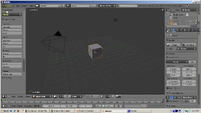
We'll work with the default cube. It's selected and in Object Mode. Go to the Edit buttons (F9) and press Tab to go into Edit mode. Press the Subdivide button, in the Mesh Tools panel, three times. Rotate the view, using either the middle mouse button or alt-Left Mouse Button if you enabled Emulate 3 Button Mouse in the Preferences window. We're in Vertex Select mode. Position the 3D Cursor at one of the corner vertices. Hold the Alt key down and press the Right Mouse button. Doing that, selects not just the vertex (which is what Right Mouse button does just by itself), but the entire edge that the vertex belongs to.
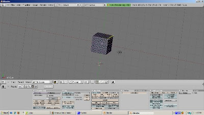


Press the A key to deselect the vertices.

Now hold the Alt key down and select a vertex that is not on the outside edge but instead is inside the cube. This time, an entire loop of edges is selected - the loop that that vertex belongs to. The loop could be horizontal or vertical.
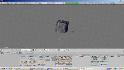


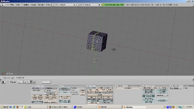
Press the A key to deselect everything. You can also select the perpendicular range of faces to which the edge belongs by holding both the Control key and the Alt key at the same time. To illustrate, press the Control key and the Alt key at the same time, and select a vertex. What is selected is the faces on the edge perpendicular to the vertex.
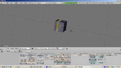


You can add to the loop selection, in effect selecting multiple loops, by holding the Shift Key down as well as the Alt Key. Hold the both the Alt and Shift keys and select an unselected vertex. Now you have selected two loops. If the loop includes all the vertices that form a face, those faces will be selected as well.
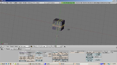


If you feel particularly ambidexterous, try holding the Control, Alt, and Shift keys down at the same time, and select another vertex. You then add to the faces selected before.

Loop selection works in edge select mode as well. Holding the Alt key and then clicking the right mouse button selects the loop to which the edge belongs to. Press the A key to deselect everything. If we go into Face Select mode, we see that loops of faces can also be selected this way. Hold the Alt kay, and with the 3D cursor on a face, press the right mouse button to select a face loop. Hold both the Shift key and the Alt key, select an unselected face with the right mouse button, and the loop in which the selected face belongs is added to the selection.
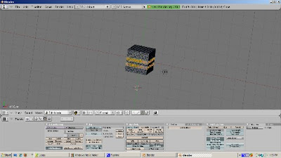


Selecting loops of vertices, edges, or faces, can make the selection process much more precise than box selection or selection of individual vertices, edges, or faces.

Creating Loops On A Cube

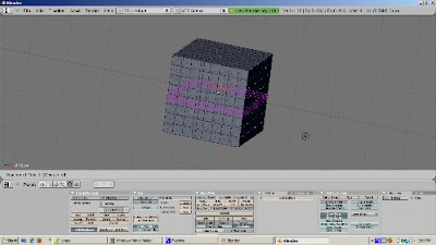
You can add edge loops with the Loop Subdivide tool (Control-R). To illustrate, position the cursor on an edge of the cube, and press Control-R. A magenta square shows where the new loop will be cut. However, you actually have more control over where the loop cut will occur. Press Enter.


Now you see both the proposed new loop, and a green line, which is the edge along which you can slide this loop. This is called "edge slide mode". A green line, showing the edge along which the loop can be cut, displays. You can scroll the edge up and down along the green line. Press Enter when you get to the position of the new edge that you want.

You can create more than one edge loop at a time. Position the cursor at an edge along where you would like to cut and press Control-R. Now, instead of pressing Enter, press the + key on the numeric keypad. This adds a loop cut, allowing you to create two loop cuts at a time. You can press the + key on the numeric keypad to add another loop cut, or you can press the - key on the numeric keypad to subtract 1 loop cut. Then press Enter. Edge Slide mode does not work when you create more than one edge loop. Instead, the loops are split evenly along the edge.


Creating Loops On A UV Sphere

Let's start with the default scene by selecting Load Factory Settings from the menu. Delete the default cube (press the Delete key, then press OK to accept the delete). Add a UV Sphere (Space - Add - Mesh - UVSphere), accepting the default settings of 32 rings and 32 segments. Press Tab to go into Edit Mode. Press A to deselect everything. Press Control-R. You can create edge loops either based on rings (going left and right) or segments (going up and down). Lets add an edge loop based on a ring. Press Control-R, selecting a horizontal edge loop to create. This selection works the same way as for a cube. Press Enter, to go into Edge Slide mode. Position the loop where you want and press Enter. However, for a ring, the edge loop only is created on half the UV Sphere. Press Control-R, then Enter. Slide the edge where you want it. Then press Enter. Rotate the UV Sphere and you will see the result. To get the edge loop to go around the UV Sphere, you will need to create the corresponding edge loop on the other side of the sphere.
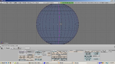


You can add more than one loop cut using the + key on the numeric keypad, and subtract using the - key on the numeric keypad, as with the cube.

Control - Alt - Right Click and Shift - Control- Alt - Right Click work the same way on a UV Sphere as on a cube. You can create a loop of faces perpendicular to the edge you select with Control - Alt Right Click, and extend the selection if you somehow manage to hold Shift, Control, Alt, and Right Click while the 3D cursor is on an unselected face.

As you can see, selecting and adding loops can make your mesh modeling more precise when you're adding detail. These techniques work on any mesh, not just the cube or UV Sphere. Try them with a torus, or with Suzanne, and you should get the hang of loop selection and addition quickly. Happy Blendering!
Friday, November 27, 2009

Incredible Machines Book


There's an exciting book coming out soon, called Blender 3D 2.49 Incredible Machines. The video shows an example of what the reader will be able to create, using Blender 3D to model the entire scene and setup all lights and materials with LuxRender. In LuxRender we will use an incredible feature called Light Groups to control all lights on the scene, with the image still rendering. Notice that we can turn on and off all lights and see the result in real time, and there are lots of other possible adjustments like the temperature of light and much more.

The video is based on the book's third project. It was created by the author, Allan Brito. Allan is an active member of the Blender development community. He's a Brazilian architect who specializes in information visualization. This is his 3rd Blender book.

This book will show you how to use Blender 3D for mechanical modeling and product visualization. Through the pages of the book, you will find a step-by-step guide to create three different projects: a fantasy weapon, a spacecraft, and a giant robot. Even though these machines are not realistic, you will be able to build your own sensible and incredible machines with the techniques that you will learn in this book along with the exercises and examples.

If you want to model machines and want to understand in depth industrial uses of Blender, this sounds like a book to examine closely.

Wednesday, November 25, 2009

2.50 Alpha 0 Tools Menu

Join my Blender 3D forum, where you can network with other Blender friends and get your Blender 3D questions answered.


November 24, 2009 marks a milestone for all Blender users because it is the release date of Blender 2.5 Alpha 0. While there is still much work to do, the release of Alpha 0 means that Blender 2.5 is formally open for user comments, testing, and feedback, at Blender Foundation's blender.org site.

You can download Alpha 0 from Blender.org.

You should also read the Alpha 0 Release Notes. These give us a much clearer path of where Blender 2.5 is headed.

Some time ago, I did a Blender 2.5 Sneak Preview Video, based on a pre-alpha version of 2.5. Although much of what I discussed is still valid, Blender 2.5 has evolved since then. Also, my understanding of certain features is clearer now than it was 2 months ago. So I thought it would be a good time to revisit, highlighting the new ways of doing things. This tutorial focuses on a particularly interesting new feature, the Tool Shelf, which reorganizes access to Blender tools into one menu.


Before we start on the Tool Menu, note that the Startup Screen has a window with links to places where we can get the latest information about Blender 2.5 - the Release Log, the Manual, the Blender.org Web site, the user community, and the Python API reference. For example, clicking the Manual link opens up a browser window with the Blender 2.5 manual, which is a wiki. I encourage you to check these links out because Blender 2.5 is developing rapidly and you don't want to miss out on the newest goodies.

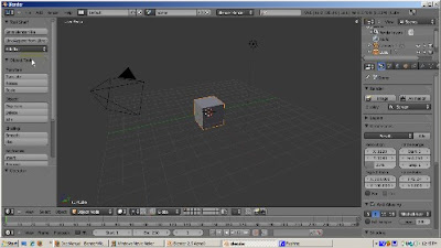
You get rid of this initial splash screen by left clicking on it. In Blender 2.5, the default scene still consists of the cube, camera, and lamp objects. The Tool Menu, what we're going to focus on, is the menu at the left side.


There are actually three sections to the menu. The top most section, the Tool Shelf, initially contains no tools. Its purpose is to give you the flexibility of adding your favorite tools, available from the click of a button. You can add a tool by clicking the Add Tool button. A list of tools displays. You can select one of those, but actually the best way to add a tool is to search for it. Let's suppose you want to save your .blend file frequently and want a button to do that. Instead of scrolling down the list of choices - there are a lot of them because it's all the possible things you can do in Blender - go to the search box (the box with the magnifying glass icon), and type the word Save. You get a list of all the Blender tools with the word Save in it. Choose Save Blender File. Now you can save the file with the click of a button. You can add as many buttons as you want to the Tool Shelf. Maybe you also append objects from libraries often. You can add the Link/Append From Library button. You can easily customize the Tool Shelf to include all the things you do in Blender frequently, without having to wade through a maze of buttons, and panels.


The next group of tool menus actually changes depending on what mode you are in. Blender starts up, as it did before, with the default cube selected and in Object Mode. Since Object Mode is selected, the tools available in Object Mode, such as Translate, Rotating, and Scaling, Smoothing, and Inserting Keyframes, display. To show how these choices change, press the Tab key to go into Edit Mode. Note that the indicator shows that edit mode is active. The tools that are applicable to meshes, such as Extrude, Subdivide, Loop Cut, as well as Translate, Rotate, and Scale, now display.

Click Tab again to go back to Object Mode. Note that the Object tools are available again. To demonstrate the bottom part of the Tool Menu, let's scale the cube up, to 3 times its original size. We're going to try to do it through the GUI but will not be successful. What would have happened in Blender 2.4x is that you would have to bring up the Transform Properties menu and change the size. This means you would have had to know about that menu. In 2.5, the options for Resize automatically display at the bottom of the Tool Menu. You can resize by changing the values there. Also, you can scroll down to get all the options available when resizing.

Now let's duplicate the cube. Press the Duplicate key. Just like Shift-D, which still works, the cube is duplicated. Move the new cube away from the old cube to see. Note that the bottom right part of the Tool Menu changed to show the options for duplicating an object. By changing the options, say to make a linked duplicate, you chane how Duplicate works. This gives you immediate visual feedback.

Another neat feature is Repeat Last. Click on Repeat Last. The last operation - in this case the duplication - is repeated. Move the new cube away from the old cube and you can see it. Repeat Last works for most operations. If you're doing some operation, like extruding or scaling, or creating edge loops, a number of times, you can save a lot of time by clicking on Repeat Last.

You can see the tools available in other modes by switching mode. Sculpt Mode, for example, shows the various brushes and settings for each type of sculpting. Weight Paint shows the Weight Paint tools. Vertex Paint shows the vertex paint tools, and so on. The specific options for each tool are on the Tool Menu, at your fingertips. This should help make your workflow more efficient.


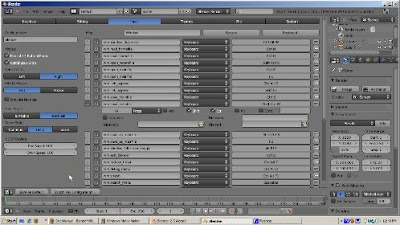
Another powerful addition in 2.5 is that the shortcuts are totally configurable. Go to the User Preferences and select the Input panel, which is selected by default. If you wanted Save File to be something other than Ctrl-W, first click the Edit button to make the keys editable. Then, find where Save File is stored. Expand the choice by clicking on the left arrow. You can change the keypress to something else, say, Control-Shift-W. You can do this for other functions. If you want these changes to be permanent, click the Save As Default button. Otherwise, the changes will be lost when you exit Blender. You can also save your key maps. The idea is that, if you use another modeling package, such as Maya, you can map the operations you used there into Blender.

I hope this gives you a taste of the new Tool Menu in Blender 2.5 alpha 0. Although everything is subject to change, something this fundamental is likely to be around when Blender 2.5 is finally released into production.

Tuesday, November 24, 2009

2.49b Append and Link

Join my Blender 3D forum, where you can network with other Blender friends and get your Blender 3D questions answered.


Suppose you have created a complicated scene, complete with a neat texture, materials, animations, and whatever else. You might want to reuse the scene, or objects in it, in another blend file. Or, you may be collaborating with others. One person does the textures and materials, another does the animation, a third is setting up the camera, and so on. How can everyone work on his or her own piece of the project and have it all come together in one final blend file? Fortunately, Blender comes to the rescue. Blender has powerful features - called Append and Link - which lets you import all sorts of things from other .blend files into your .blend file. The goal of this tutorial is to show you how you won't have to reinvent the wheel. Instead, you just use Append and Link to reuse what already has been created.

We are first going to create a blend file with some objects, materials, and scenes that you might want to share with others.

1) Select the default cube. The cube has a default material. Go to the F5 (Shading buttons). Click the Generate An Automatic Name button to make the material something descriptive. Blender makes an attempt at creating a realistic name for the material. It's name is now Grey.

2) Add green monkey (Space - Add - Mesh - Monkey). Move the monkey 2 blender units to the right to separate it from the cube. Press F5 (Shading) and click Add New. Make material green (R=0, G=1, B=0). Name the material something descriptive, using the Automatic Name button. The material is now named LightGreen.

3) Create a new, empty scene by going to the Scene list and clicking ADD NEW. Name the scene SphereScene. Move the 3D cursor to the left and add a UV Sphere, with the default settings of 32 rings and 32 segments (Space - Add - Mesh - UVSphere).

4) Save this blend file. Call it SourceFile.blend.

5) Now let's see how to get stuff from that file. Start by going to the default Blender setup. Select File - Load Factory Settings, and accept Erase All. We're going to get rid of everything, not just the default cube, but the lamp and the camera as well. To do this, press the Home key, which shows all the objects. With the default cube highlighted, press the Shift key and right click on the lamp. Then press the Shift key and right click on the camera. Press the delete key and accept the defaults, deleting all the objects. We now have a blank scene, with no objects.

6) To see what objects we can import, go to File - Append or Link, or press Shift F1. Select Object. All the objects in the SourceFile blend file are listed. Select Suzanne. Then click Load Library. Suzanne is appended to the new file. Append is the default mode. Note that she is green because she was green in the source file.

We can change Suzanne's color. With Suzanne highlighted, press the shading buttons (F5) and change her color to red by settng R=1, G=0, and B=0. However, if we press F12 to render, we get the error message "No Camera". That's because we don't have a camera, or a lamp for that matter.

So let's append the lamp and the camera as well. We can append more than one object at a time. Select File - Append or Link. Select the SourceScene. Instead of left clicking, hold the Shift key and right click on the camera. Then hold the Shift key down and right click on the lamp. The lamp and camera text should be highlighted. Click the Load Library button. The camera (named Camera) and lamp (named Spot) are now appended to the file. Press F12 to render. The monkey now renders properly.

7) Let's see how Link differs from Append. Select File - Append or Link, selecting the SourceScene again. Select the Cube (left click). Before loading the cube into the blend file, click the Link button. This will create a link to the cube. Click the Load Library button. The cube is linked into the file. Now let's try to change the cube's color by going to the Shading buttons. Guess what! We cannot do it! We get the message that we cannot edit external libdata.

Link differs from Append in that while Append gives us a copy of the object and lets us change it, Link points back to the source object. By the way, not only can the color can't be changed, but any aspect of the data cannot be changed. A linked object can only be changed at the source. You cannot move it, rotate it, or scale it.

You might use Append to make a copy of an object but to be able to change it in the new blend file. Link is a better choice if you don't want anyone to change the object, such as a building that will have the same characteristics from one file to another.

8) Other things can be appended, such as materials. Let's load the factory settings again to start with the default Blender setup. Select the default cube and press F5 to go to the Shading buttons. Supppose we want to use the green material in the SourceFile. Instead of setting the sliders, we can select File - Append or Link and select SourceFile.blend. Select Material. Choose LightGreen, and click the LoadLibrary button. Now if we click the Materials, we see that LightGreen has been appended. The "O" before it means that there is no object that has that color, i.e. that LightGreen is an "orphan". If we click on it, however, the light green material is assigned to the cube. Now that the light green material has been assigned, the original material (called Material) has the "orphan" designation. An orphan material will be deleted when the file is saved. If you want to keep that material in the file, you need to create a Fake user by pressing the "F" button. You can create a blend file with your favorite materials, to use as a library, and append them as you need them.

9) You can append or link entire scenes. To illustrate, select our source file, choose Scene, and append the SphereScene by clicking on Load Library. The SphereScene is now available. Many other things, such as groups, meshes, and text objects, can be appended or linked.

Using append and link can save you hours of time and allow you to collaborate Blender development with others. You can split the workload and append or link each piece into the final product. I hope this gives you some ideas about how to use this powerful Blender feature. Happy Blendering!

Thursday, November 12, 2009

2.49b Depth of Field Nodes

Join my Blender 3D forum, where you can network with other Blender friends and get your Blender 3D questions answered.


Hi. The eye naturally focuses on sharper objects in a scene and tends to overlook blurred objects. Depth of Field (DOF) is a technique in which you highlight objects in focus, giving them the illusion of being closer to the camera, and blur out the parts of the scene that are not as important. You can use this to force your viewers to focus on the objects you consider important. Using Blender's composite nodes, with some mathematical trickery, you can set up Depth of Field.

So let's get started. Fire up Blender, delete the default cube (Right Click, Delete key, and Enter to confirm). Add the monkey mesh (Space - Add - Mesh - Monkey). Let's make the monkey green. Press F5 (Shading). Then click Add New to add a new material. Set R=0, G=1, and B=0. Go to the Edit buttons (F9). Press the Set Smooth button to make Suzanne more presentable.

Let's make more Suzannes. Click the Modifier button, at the extreme right. Add an Array Modifier. Make sure Relative Offset is clicked. Set X= -1, Y=0, and Z=0. Set Count = 8. Press F12 to render. We now have 8 monkeys, each a bit farther away from the camera than the previous one. The last two monkeys are out of camera range. To fix this, press N to bring up the Transform Properties window. Set LocX to 3. Now there are 8 monkeys in camera range.

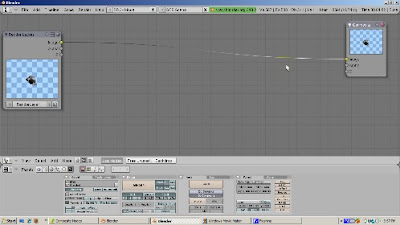
Suppose we want our viewers to focus on the first monkey and gradually blur the rest of them as they get further from the camera. We can achieve this effect with Composite Nodes. To do this, change the window type of the 3D Viewport to Node Editor. We start out with two nodes. The input Render Layers node is our original scene before the composite node magic is applied. The output Composite node is the final, composited result. Move the Composite node all the way to the right.

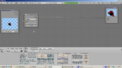
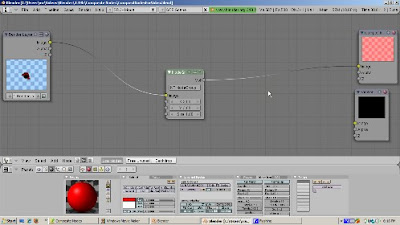
Add a Map Value node (Space - Add - Vector - Map Value). Map Value takes information and maps it into a range of values. Map Value can also add a number (the Offset), as well as multiply by a number (the Scale) from the input. We're going to play with the offset and scale in a minute. In this case, we are going to map the Z value, which is the distance, in Blender Units, of each pixel, from the camera. Connect the Z socket of the Render Layers node to the Value socket of the Map Value node.

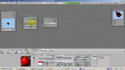
Next, add a Color Ramp node (Space - Add - Converter - ColorRamp). The color ramp gives us a visual representation of the Z values, with values from 0 (black) to 1 (white), Connect the Map Value's Value socket to the Factor socket of the Color Ramp node. Then, connect the ColorRamp image socket to the Composite Node image socket.

Right now the compositor shows all white. That's because all the monkeys map to a value of 1 or greater. The first monkey is about 5 Blender Units from the camera. With this mapping, the monkeys all map to white.

However, if we adjust the offset to -6 and the Size to .1, we get an interesting falloff from black to white. What happens is that for distances between 6 and 16 Blender units, we map a value between 0 and 1. Here's an example. Take a pixel at 10 Blender Units from the camera. First subtract 6, to get 4, then multiply 4 by .1, yielding a value of .4, which maps to a grayish color 40% between black and white. Any Z distance less than 6 produces black. A value greater than 16 produces white. We can translate this falloff into a gradual blurring.

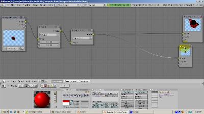
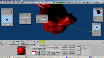
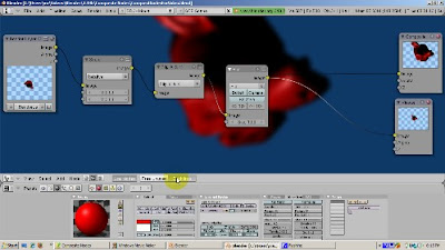
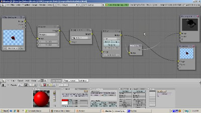
To do this, add a Blur node (Space - Add - Filter - Blur). Connect the Image socket of the Render Layer node to the Image socket of the Blur node. That will feed the original scene to the blur node. Then, connect the Image socket of the ColorRamp node to the Size socket of the Blur node, feeding the adjusted Z values to the Blur node. Connect the Image socket of the Blur node to the Image socket of the Composite node.

You need to fiddle around with the X and Y values in the blur node to set up the exact amount of blur falloff. I found that X=6 and Y=6 worked well for focusing on the first monkey and gradually fading out the others.

We're ready to render. Go to the scene buttons (F10). Press the Do Composite button to tell the Renderer that we are using composite nodes. Press F12 to render. You should get the depth of field effect we're aiming for.

That's it. I hope this gives you some interesting ideas for highlighting objects in your scene using depth of field. Happy Blendering!

2.49b Vector Blur


Vector blur is a great way to add realism to your animation. Your eye naturally sees moving objects moving as a blur, because that is how your brain processes the motion. Without some sort of blurring, animated moving objects don't look as if they are realistically moving. Blender's animations are by default rendered as a sequence of perfectly still images. This is unrealistic, since fast moving objects do appear to be 'moving', that is, blurred by their own motion, both in a movie frame and in a photograph from a 'real world camera'.

To obtain such a blurring effect with moving objects, Blender can be made to render the current frame and some more frames, in between the real frames, and merge them all together to obtain an image where fast moving details are 'blurred'. The goal of this tutorial is to demonstrate how to blur moving objects in Blender.

First, we'll create a simple animation. We will animate the movement of the cube across the screen, over 50 frames. With an animation speed of 25 frames per second, that produces a 2 second video, one second going across the screen, the other second going back.

1) Go to the SR-1: Animation view.
2) Press the N key to bring up the Transform Properties window. Set the X location to -7, the Y location to 0, and the Z location to 0.
3) At Frame 1, press the I key and insert a Location key frame.
4) Go to Frame 25. Set the X location to 4, the Y location to 0, and the Z location to 0.
5) Press the I key and insert a Location key frame.
6) Go to Frame 50. Set the X location to -7, the Y location to 0, and the Z location to 0.
7) Press the I key and insert a Location key frame.

8) Go to the Scene buttons (F10), and set the animation to 50 frames.
9) In the Format panel, set the animation type to your favorite. I used the compressed AVI format with the CamStudio Lossless Codec, version 1.4, for compression.
The video will be created in the Output directory (/tmp by default), with a filename of 0001_0050.avi. Set the output directory to the folder where you want the video to be saved. If you chose a QuickTime movie, the filename would be 0001_0050.mov.

10) Hit the ANIM button. I will pause the video while the animation is being rendered, as I will do for the other animations in this video. The render took 1 minute, 10 seconds.

The animation does indeed have the cube move back and forth, but the motion of the cube is not realistic. The cube just moves in a straight line uniformly, without the blurring effect of motion.

With the help of the Node editor, we can introduce vector blur to this animation and compare. To do this,

1) Go to the Render Layers tab of the Scene button. Vector blur takes a special Vector (VEC) rendering pass, which is not rendered by default. Find the VEC button and enable it. Vector Blur requires the COMBINED, Z, and VEC passes. The others you may need to render the scene exactly as you need it.

2) Change the 3D view to the Node Editor. Press Control-Down Arrow to maximize te Node Editor. Click on the face, for composite nodes. Then click the USE NODES button. There are two default nodes, the input node (Render Layers) is the scene as rendered without compositing. The other node, the Composite node, is the final result of the compositing process.

3) Move the Composite Node all the way to the right, to make room for the Vector Blur.

4) Add the Vector Blur filter (Space - Add - Filter - Vector Blur). Accept the defaults. Connect the Image socket of the Render Layer to the Image input of the Vector Blur node. Connect the Z socket of the Render Layer node to the Z socket of the Vector Blur node. The Z socket stores the Z information - the distance of the cube from the camera. Connect the Speed socket of the Render Layer node to the Speed socket of the Vector Blur node. The Speed socket is really the key to blurring the cube's movement. You can play with the defaults. Increasing the number of samples, for example, makes the vector blur more realistic but slows down the rendering. Also, you can control which moving objects are blurred. A speeding sports car should be blurred, but bystanders should not.

5) Connect the Image output socket of the Vector Blur node with the Image socket of the Composite node.

The noodle (the node setup) is complete. Go back to the Scene buttons and click the Do Composite button. Press the Render button. Look at Frame 1. The monkey is blurred.

6) Time to animate. Click the ANIM button. Pause until the 50 frames are rendered. The render took 1 minute, 47 seconds.
Now you see the cube blurred while it is moving --- a much more realistic animation. Think of a fast sports car speeding by you.

Blender has another way to implement blurring a moving object: the Motion Blur option. To demonstrate that, click the MBLUR button in the Scene panel. Turn off Do Composite because motion blur doesn't rely on nodes. MBLUR is very slow because it renders each frame up to 16 times. The number of samples is controlled by the OSA setting, which is 8 on my computer. Eight renders per frame is mighty slow. The renderer calculates the position of each object and then averages the positions out. It is more accurate than Vector Blur, but at the cost of a LOT of time. Here is the cube animation with motion blur.

To summarize, Blender provides you with two options, Vector Blur and Motion Blur, for making your moving object look more realistically blurred as the object moves in the scene. For most applications, especially in the Game Engine, Vector Blur will work well. Happy Blendering!

Wednesday, November 11, 2009

2.49b World Colors


Blender provides a number of useful settings to set up a background color, image, and texture, as well as the special effects of mist and stars. These settings are important because they interact with many other parts of your scene, such as lamps, materials, and textures on your objects. You need to be aware of how the world settings work even if you don't change them often. The purpose of this tutorial is to explore the one setting you can't miss - the world colors.

First, let's set the scene. Delete the default cube (Right click, press the delete key, and press Enter to confirm). Add a UV Sphere (Space - Add - Mesh - UV Sphere), accepting the default of 32 segments and 32 rings. Press the Set Smooth button in the Edit panel to smooth out the UV Sphere. Add a subsurf modifier by pressing the Modifiers button and selecting Subsurf. Set the levels to 2. Switch to Front view (Num1). You know you're in Front view if the blue Z arrow points upward. Make the UV Sphere red by pressing the shading buttons (F5), pressing Add New, and setting R=1, G=0, and B=0.

Press the Home key to see the lamp, the sphere, and the camera. Move the lamp near the camera. Select the lamp first, then the camera, then Control-P to make the camera the parent of the lamp. We want to be able to position the camera so that it can track the UV Sphere and we can see the horizon. Go to the Object buttons (F7), then go to the Constraints button, at the far right. Select the Track To constraint. Enter the word Sphere in the Ob: area. Click the -Z button, the last - sign in the To: area, and the Y button in the Up: area. No matter where the camera is positioned, its focus is on the sphere.

Press F12 to render. Note that the sphere is red and the background color is blue. The background color comes from the World color settings, which you get to by pressing F5 (Shading), and then pressing the World icon in the Subcontext area. The preview square shows the default background color, which is derived from the Horizon color - Red=.05, Green=.22, and Blue=.4. Move the camera closer to the ground (the horizontal red line across the window) and press F12 to render. The background color is blue no matter where you position the camera.

There are many ways to change the background color. The first is just to change the horizon color directly. Make the background magenta by setting R=1, G=0, and B=1 for the horizon colors.

That's simple enough. You can also make the background a gradient of two colors, from the top to the bottom. Let's make the background color a gradient, from blue at the top to orange at the bottom. To do that, set the Zenith color to blue (ZeR=0, ZeG=0, and ZeB=1) and the Horizon color to orange (HoR=1, HoG=.5, HoB=0). Click the Blend button to activate color blending. Press F12 to render. Move the camera around the cube and render. No matter where the camera is positioned, the background is the same blue to orange blend.

Click the Real button. Now there are two gradients. The first, from the zenith (the top) to the horizon, goes from blue to orange. The second goes from the horizon to the nadir (the bottom), from orange to blue. If the camera has the horizon line (the red line in the 3D view) in range, it's rendered as an orange line, as a real horizon. However, if the camera is directly overhead or beneath the horizon, the orange horizon line is not rendered.

Click the Paper button. With all three buttons active, the zenith to horizon to nadir gradient is always rendered, no matter where the camera is positioned.

Of course, if you have a real sky image, you can use it instead of the colors. To do that, you add an image texture. Go to the Texture and Imput panel and select the first texture rectangle. Name the texture Sky. Then press F6 to go to the Texture panel. Click the Load Image button. Select the Sky image. Then go back to the World buttons, select the Map To panel, and click on Hori, for Horizon. Press F12 to render. If you click the ZeUp and ZeDown buttons as well, the Sky image is rendered no matter where the camera is positioned.

That's it. I hope this gives you a good grasp of how to use world color settings. Happy Blendering!

Friday, November 6, 2009

2.49b Composite Nodes


Nodes are a powerful Blender feature, allowing you to change how your scene renders, to combine images and videos, and to do many types of special effects. Compositing is a critical part of the video production process. The purpose of this video is to make you comfortable moving around in the Node Editor and to introduce a some basic image effects.

Let's delete the default cube and have fun with Suzanne. So highlight the cube (right click), press X to delete and Enter to confirm. Then add Suzanne (space-add-mesh-monkey). Press F9 to go to the Edit buttons. Press the Set Smooth button to make her look a bit more presentable. Add a red material by pressing F5 (Shading), then the Add New button to add a new material. Set the R to 1, the G to 0, and the B to 0.

To set up node based rendering, press F10 to go to the Scene buttons. In the Anim panel, press the Do Composite button. When you do this, instead of the scene rendering, the result of your composite node processing renders when you press F12.


To go to the Node Editor, change the View type to Node Editor. Blender supports material nodes and texture nodes as well as composite nodes. To enable Composite Nodes, click the Face icon. Then, click on the Use Nodes button.


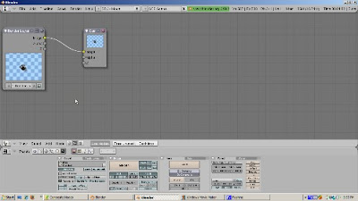
Two puzzling rectangular objects display. On the left is the Render Layers node. On the right is the Composite node. You can resize a node by clicking on the lower right part of the node and dragging. The nodes are connected by a black wire, from the yellow Image button on the right side of the Render Layer node to the yellow Image button on the left side of the Composite node. What's going on?

Composite nodes really have three types, Input, Output, and different types of things you might do to the input before you render the output. Think of compositing as similar to going to the barber shop. Your head, before you get your haircut, with unshaven and with unkempt hair, is the input. The barber can do a number of things - give you a shave, wash your hair, cut it short, and so on. These are like processing nodes. The end result - the output - ends up in the Composite Node. The first big rule of compositing is: There Can Only Be One Composite Node.

The Render Layers node is the input - your scene before anything is done with it. The Composite node is the result. Node setups can get very confusing. The easiest way to set them up is to place the input nodes (there can be more than one, because we might combine things, such as a scene with an image), on the far left, and the output node, the Composite node, to the right. The processing nodes are in the middle, best placed in logical order from left to right.

Move the Composite node all the way to the right. Moving is similar to moving in the 3D window. Press the Right arrow key to select the Composite node, then drag it all the way to the right. The wire follows along.


Press F12 to render. Suzanne renders as if there was no compositing active. You also see a thumbnail of the rendered scene both in the Render Layers node and the Composite node. That's because this is like walking into the barber shop, seeing the long line, and walking out. Nothing was done.

OK. Let's do some stuff to Suzanne. How about making her 3 times bigger? Easy. Instead of going back to the 3D view and scaling her up, you can do it in the Node editor. Add a Scale Node (Space - Add - Distort - Scale). Nothing happens yet. You need to connect the wires. To do this, connect the Image socket (that's the yellow Image dot) on the right side of the Render Layers node to the Image socket on the left side of the Scale node. This tells the Node editor to pump the scene, with Suzanne, into the Scale node. Set the X and Y values to 3, to indicate how large to scale Suzanne.

Next, connect the Image socket on the right side of the Scale node to the Image socket on the left side of the Composite node. This tells the Node editor to take the new, larger Suzanne, and add it as input to the Composite node. Look at the image on the Composite node. It already shows the bigger Suzanne. If you press F12 to render, Suzanne also renders larger.


That's a good start. How about flipping her upside down? Easy. Add a Flip node (Space - Add - Distort - Flip). Connect the Image socket on the right side of the Scale node to the Image socket on the left side of the Flip node. From the dropdown, select Flip X & Y. Now connect the Image socket on the right side of the Flip node with the Image socket on the left side of the Composite node.


The path is clear. Suzanne is scaled and then flipped. You can see each step. By the way, the 3D view hasn't changed. Suzanne is still her old self. Change to 3D view, look, and change back to the Node editor.

The Viewer node, another type of output node, lets you view Suzanne's progress. To add a Viewer node, press Space - Add - Output - Viewer. Automatically, the Viewer node is connected, via the Image socket, to the last node selected. A handy button is the Use Backdrop button, which displays the most recently selected Viewer node. You see Suzanne both scaled and flipped.


We can see Suzanne after she was scaled but before she was flipped. To do that, cut the connection between the Flip node and the Viewer node by pressing the left mouse button and dragging across the wire. Then, connect the output Image socket of the Scale node to the input Image socket of the Viewer node. Now Suzanne is scaled but unflipped.


Click the Backdrop button to get the regular background. Let's blur Suzanne, giving the illusion of fuzziness. Blur is a filter node. So press Space - Add - Filter - Blur. Connect the Image socket on the right side of the Flip node to the Image socket on the left side of the Blur node. Set X and Y to 10, specifying the blur amounts. Then connect the Image socket on the right side of the Blur node with the Composite node's image socket. Click the Backdrop button.


Now let's make Suzanne black and white. Add a Converter node to do that (Space - Add - Converter - RGB to BW). Convert the Image socket on the right of the Blur node to the Composite Node image socket.


Many of the keys you are familiar with in navigating the 3D window work in the node editor. Right click selects a node. Shift Right click on another node extends it. X deletes the selected nodes. Control-Z corrects your error.

You can group nodes when you have a lot of them. Let's say you really like to scale, flip, blur, and make objects black and white. You can create a group out of these nodes. Select all of them press Control-G. You've created a nice node group, cleaning up the diagram a lot. Node groups can be copied and even exported to another blend file, which is nice because you won't have to redo all those steps each time. The tab key shows the nodes in the group. If you change your mind, Alt-G undoes the grouping.


To summarize, we've enlarged Suzanne 3 times, flipped her over, blurred her, and got rid of her red color - all without touching the underlying 3D view, which you can see in the Render Layers node. This just scratches the surface. I hope this gives you a good start on compositing nodes in Blender. Happy Blendering!

Monday, November 2, 2009

Blender Python 1: Setup


In addition to everything else, Blender is a programming environment, with Python its language of choice. Even if you don't plan on creating Python scripts in Blender, you should understand the Python environment. Python is how Blender talks to you. The purpose of this tutorial is to introduce you to Blender's Python environment. Understanding this environment should help you understand how Blender works as well. Of course, if you want to write Python scripts to make Blender behave exactly how you want, becoming familiar with the Blender Python environment is the first step. Even if you don't program, just understanding how to run a script will allow you to run Python programs, called scripts, written by others. For starters, go to the Blender Python Scripts Catalog.

Did you ever wonder what the purpose of the first window, and what the message:


Compiled with Python 2.6.2
Checking for installed Python... got it!


means? Does it have anything to do with big, poisonous snakes?

No. That first window is Blender's Python console. That message, which is what you should see as well, means that Blender found a good Python installation on your computer and that it could run Python programs. Blender also reports the Python version it found. You should, in general, go with the latest, most stable release of Python, which you can find at:

http://www.python.org

Python programs, incidentally, are called scripts and have the same meaning scripts have in the theatre. They're instructions for Blender. Blender uses Python scripts everywhere - to create objects, to move objects around in a scene, to animate objects, to add materials and textures, and so on.

Blender has two windows that were designed for interacting with Python. The Scripts window, the one with the snake icon, was designed to run Python scripts. The scripts are grouped into areas such as Mesh, Object, and UV. To run a script, select it from the menu. One commonly used script is to save the UV Face Layout to a file, for use with an image editor such as The Gimp or Photoshop. When you run the script, a screen with options for the UV image file displays. You can accept the defaults, or change them, and then press OK. The script will then run, asking you where you want to create the face layout file.

Blender has a built in Scripting setup, which works well if you want to create Python scripts in Blender. To access this window, go to the SR:5-Scripting view, which you can select from the dropdown menu. There are three windows: the 3D viewport, on the left; the Buttons Window, with the Scripts area highlighted, at the bottom; and the Text window at the right.

You have probably downloaded blend files with notes in the Text window. That's a great use for the text window. Another is to write Python scripts for Blender. Let's write our first Python script, a message to the Blender console announcing our presence. Type:


print "Ira was here."


in the Text window.

To run a script, you can either press Alt-P, or from the Text Menu, select Run Python Script. Press Alt-P. Seemingly, nothing happened. Blender is strangely silent if things go OK. Actually, the script run. To see the result, go to the Blender console, and the message "Ira was here." displays.

Blender will, however, tell you when you have made a programming error. Let's introduce an error. Text needs to be enclosed on each side by double quotes. Delete the last double quote. Press Alt-P. You get the following message:


Error: Python Script Error
Check console


Now that you have gotten this far, you know where to look. Click on the console window. You get the message:


SyntaxError: EOL while scanning string literal
File "Text" Line 1


and it shows you where it thought the error was. Actually, the error isn't quite where the message is pointing, but you have to give Blender a gold star for trying to be helpful.

Go back to the text window, add the double quote back, press alt-P, and check the console window. Everything is OK again.

Here are some formatting tips. Press the computer window icon. This makes the text window full screen. If your script is large, it's easier to have the window full screen so you won't have to scroll up and down as much. To return to the text window's original size, press the computer window icon (the screen is divided into 4 parts).

The next button displays line numbers along with the code. This can be very handy, especially considering that Blender's error messages give you the line number. Line numbers make it easier for you to get to a particular line.

The next window enables word wrap. Generally you don't want that button enabled when you are writing a script, although it is handy if you are writing notes or free form text in the window.

The "AB" button enables syntax highlighting. This is useful in coding to give you hints as to the proper syntax of a line of code.

The snake button enables Python text plugins. Text plugins can give the Text editor more power. You can find text plugins by going to the Text menu and selecting Text Plugins.

The Screen dropdown lets you change the font size. The code currently displays with a font size of 12. You can change it to 15 by selecting 15. Your choices depend on the fonts installed on your computer.

The Tab: selector lets you change the number of spaces that the editor inserts when you press the Tab key. Python syntax checks based on having the code properly tabbed. Making the indent larger helps the readability of the code as well. You can add a tab by placing the cursor at the beginning of the line and selecting Indent from the Format menu. You can also unindent.

Highlight the line "Ira was here". You can comment it out by selecting Comment from the Format menu. Commenting a line of code means that the code will not execute, i.e., run. To show this, press Alt-P to run the program. The message does not display on the console. You can uncomment by selecting Uncomment from the Format menu. Press Alt-P to run the program again. This time the message displays on the console.

You can create more than one script in a blend file. To do this, click the ADD NEW button. A new, blank text window, titled TEXT.001, displays. Enter a line of code


print "Message from Outer Space"


Press Alt-P and check the console. The message displays.

If you save the blend file (Control-W), all the text windows are saved. You can also save individual text windows by selecting the Save button from the Text window, or pressing Alt-S. Python files should be saved with an extension of .py.

I hope this gives you a good level of comfort with Blender's Python programming environment. I plan to do more tutorials on how to use Python in Blender. There is a lot to cover, much more than can be done in a 10 minute video. Happy Blending!