Showing posts with label rendering. Show all posts
Showing posts with label rendering. Show all posts
Monday, May 17, 2010
2.49b Yafaray Tutorial
YafaRay is an external renderer (download it from www.yafaray.org) that is integrated with Blender 2.49 via Python scripts. You can add many dramatic features, such as global illumination, caustics, enhanced ray tracing, and self illuminated objects, to your renders, with YafaRay. YafaRay extends Blender's built in renderer with special types of lighting, new material options, and enhanced world settings.


Friday, February 26, 2010
2.49 Pixar Eye Tutorial
The goal of this tutorial is to make a Pixar-looking eye. The idea for this tutorial came from a post by KSF2010 on my Blender 3D Forum, at http://forum.irakrakow.com. He rendered a whale with "Pixar eyes". You can see his render at:
I was curious how to do Pixar eyes. He mentioned some tutorials on the web.
This tutorial is based on:
Iris texture: http://en.wikibooks.org/wiki/File:Iris.png
This tutorial uses the same modelling and texturing technique described in the well-known MAX tutorial by Adam Baroody.
Sunday, January 17, 2010
Free Blender Render Farms
Join my Blender 3D forum where you can network with other Blender friends and get your Blender 3D questions answered.
One of the most significant challenges for Blender users is that, when scenes become complex, with meshes containing many thousands, or even millions, of polygons, complicated physics, many texture and material channels, many render layer passes, all of which are animated, render times on even a powerful PC can become unacceptably high. These can stretch into even days or weeks. You might think that you would need a Pixar-size budget to get acceptable render times. In fact, it's possible to significantly reduce render times, I mean by factors of 10 or 100, for free. The answer is to use one of the free render farm options available. I believe that Blender, combined with using one of these render farm options, can help you to approach Pixar-like, or Avatar-like, quality videos with a fraction of Pixar's budget, or even with no budget at all. That's why I call Blender "Pixar on your laptop". I hope Pixar doesn't sue me for this slogan. My goal for this video is to show you how to either create your own render farm if you have some spare PCs hanging around, and you have a wireless Internet connection, or how you can use one of the free, open source, to grab the computer power you need.
First, here's a quick and dirty way to create a render farm with some spare PCs that you have networked. The only real requirement is that you have enabled file sharing on, say, a Public folder in your network. I don't know what operating system - Windows XP, Vista, System 7, Linux, Mac OS X, whatever - that you're working on, but I'll assume that you have some way to share files. Once you've done that, create the Blend file that you want to render. Press the Scene button (F10) and in the Output directory, enter the name of the shared folder (I entered /IRA-PC/Public just as an example). Then press the Touch and the No Overwrite buttons. What this does is allow any temporary files to stay around. Save the file. Then copy the Blend file to the Public folder, making sure the file is shareable. The last step is to go to each PC on your network, open up the blend file, and press the ANIM button. Each computer will then start up at the next unrendered frame, thus sharing the rendering load. Try it. Tell us your results by going to my blog for these tutorials, at http://blender3dvideos.blogspot.com, and adding a comment.
OK, now suppose you don't have spare PCs available and want to speed up your renders like the big guys. No problem. There are a number of free, open source, render options available. I'll show you two of them. The most commonly used one is FarmerJoe, which you can download at www.farmerjoe.info (Make sure you use the .info suffix.) I haven't installed it, but I did download the zip file. The install appears to be simple enough. Unzip the file, in Windows, run the exe file, and then run the Python script to schedule jobs. There's a Web app server to check the status of your job. Again, try it and tell us your results by adding a comment to my blog at http://blender3dvideos.blogspot.com. I'll post the full URL of the blog page on the Youtube notes to this video.
Another possibility is the University of California, Berkeley's BOINC project, which uses the spare computer cycles of PCs around the world, available for anyone to share. You can join the network, at http://boinc.berkeley.edu and trade your idle CPU cycles with other PCs. There's plenty of idle computer time to go around. Why not make use of it?
Maybe you have other ideas? If so, please share them by commenting, either on my blog at http://blender3dvideos.blogspot.com, or leave a comment on this video. If you liked this, remember to hit the Youtube Subcribe button so you won't miss any of my future Blender tutorials. Happy Blendering!
One of the most significant challenges for Blender users is that, when scenes become complex, with meshes containing many thousands, or even millions, of polygons, complicated physics, many texture and material channels, many render layer passes, all of which are animated, render times on even a powerful PC can become unacceptably high. These can stretch into even days or weeks. You might think that you would need a Pixar-size budget to get acceptable render times. In fact, it's possible to significantly reduce render times, I mean by factors of 10 or 100, for free. The answer is to use one of the free render farm options available. I believe that Blender, combined with using one of these render farm options, can help you to approach Pixar-like, or Avatar-like, quality videos with a fraction of Pixar's budget, or even with no budget at all. That's why I call Blender "Pixar on your laptop". I hope Pixar doesn't sue me for this slogan. My goal for this video is to show you how to either create your own render farm if you have some spare PCs hanging around, and you have a wireless Internet connection, or how you can use one of the free, open source, to grab the computer power you need.
First, here's a quick and dirty way to create a render farm with some spare PCs that you have networked. The only real requirement is that you have enabled file sharing on, say, a Public folder in your network. I don't know what operating system - Windows XP, Vista, System 7, Linux, Mac OS X, whatever - that you're working on, but I'll assume that you have some way to share files. Once you've done that, create the Blend file that you want to render. Press the Scene button (F10) and in the Output directory, enter the name of the shared folder (I entered /IRA-PC/Public just as an example). Then press the Touch and the No Overwrite buttons. What this does is allow any temporary files to stay around. Save the file. Then copy the Blend file to the Public folder, making sure the file is shareable. The last step is to go to each PC on your network, open up the blend file, and press the ANIM button. Each computer will then start up at the next unrendered frame, thus sharing the rendering load. Try it. Tell us your results by going to my blog for these tutorials, at http://blender3dvideos.blogspot.com, and adding a comment.
OK, now suppose you don't have spare PCs available and want to speed up your renders like the big guys. No problem. There are a number of free, open source, render options available. I'll show you two of them. The most commonly used one is FarmerJoe, which you can download at www.farmerjoe.info (Make sure you use the .info suffix.) I haven't installed it, but I did download the zip file. The install appears to be simple enough. Unzip the file, in Windows, run the exe file, and then run the Python script to schedule jobs. There's a Web app server to check the status of your job. Again, try it and tell us your results by adding a comment to my blog at http://blender3dvideos.blogspot.com. I'll post the full URL of the blog page on the Youtube notes to this video.
Another possibility is the University of California, Berkeley's BOINC project, which uses the spare computer cycles of PCs around the world, available for anyone to share. You can join the network, at http://boinc.berkeley.edu and trade your idle CPU cycles with other PCs. There's plenty of idle computer time to go around. Why not make use of it?
Maybe you have other ideas? If so, please share them by commenting, either on my blog at http://blender3dvideos.blogspot.com, or leave a comment on this video. If you liked this, remember to hit the Youtube Subcribe button so you won't miss any of my future Blender tutorials. Happy Blendering!
Monday, January 11, 2010
2.50 Animation Part 1
Join my Blender 3D forum where you can network with other Blender friends and get your Blender 3D questions answered.
Download the blend file
Watch mfoxdogg's Blender 2.50 Tour 9 Part 2 (Animation) video
This tutorial is based on the Blender 2.5 Tour 9 (Animation) video, published by Michael Fox, aka mfoxdogg. Michael works closely with the Blender developers and has detailed knowledge of all the new features in 2.5. At my blog, at http://blender3dvideos.blogspot.com, is a link to his animation tutorial, as well as to his blog at blenderlabrat.blogspot.com. He has been doing Blender 2.5 tours for a while now, as evidenced by the fact that this is Tour 9. What's nice is that Michael also frequently contributes comments to my videos as well. If you have 2.5 questions, just email him or post a response to his comment.
I won't go into nearly as much detail as Michael does. My goal for this video is to give you a basic understanding of how animation in 2.5 works, and how it differs from 2.4x animation. For one thing, animation is much easier in 2.5. For another, you can animate just about anything in 2.5. In 2.4x there were many features that you could not animate. The developers completely rewrote, and significantly improved, the animation code in 2.5.
So start up Blender 2.5. I'm using the Alpha 0 version, which you can download from blender.org. We'll start with the default cube. Just as in 2.4x, with the cursor in the 3D window, you can press the I key to insert a keyframe. You can insert combinations of location, rotation, and scale keyframes. At Frame 1, insert a LocRotScale to insert location, rotation, and scale keyframes. The timeline window is right below the 3D window.
Move the timeline slider to Frame 50. Move the cube 3 or 4 blender units to the right (Right click to select, G to grab, then drag, then press ENTER). Scale the cube up 3 times (S - 3 - Enter). Rotate the cube 45 degrees (R - 45 - Enter). Insert a LocRotScale keyframe (press the I key, then select LocRotScale). Set the animation end frame to 50 by entering 50 in the End area. Press Alt-A to animate. Note how the cube grows, moves, and rotates from Frame 1 to Frame 50. Press ESC to stop the animation.
Alt-Shift-A behaves a bit differently from Blender 2.4x. If you press Alt-Shift-A, the animation goes backwards, from Frame 50 back to Frame 1. You can see the backwards animation in the timeline, as the slider goes backwards. In 2.4x Alt-Shift-A pleys the animation forward in all windows. In the VCR controls in the timeline, you see two arrows, a left pointing arrow and a right pointing arrow. The left pointing arrow plays the animation backwards, and the right pointing arrow plays the animation forwards.
Just as in 2.4x, you can animate material properties, such as diffuse color. In 2.4x, you had to go to the material context and press I to insert a keyframe. In 2.50, the material properties are grouped together in the materials panel. Let's change the diffuse color from red at frame 1 to green at frame 25 and blue at frame 40. First, go to the materials panel by clickinig on the grey ball icon. Then go to Frame 1 by setting the current frame number. A basic goal of Blender 2.5 is that anything that you see can be keyframed. The way to do that is to right click on a property and then select Insert Keyframe. Click on the Diffuse Color rectangle. Change it to a reddish color by selecting it in the color wheel. Right click on the rectangle and choose Insert Keyframes. Keyframes are inserted for the Red, Green, Blue, and Alpha channels.
Now go to Frame 25 by setting the Current Frame slider. Click on the Diffuse Color rectangle. Change the color to a greenish color. Right click on the diffuse color rectangle. Select Insert Keyframes.
Go to Frame 40 by setting the Current Frame slider. Click on te Diffuse Color rectangle. Change the color to something blue like. Right click on the diffuse color rectangle. Select Insert Keyframes. Now press Alt-A. Now the cube grows, moves, rotates, and changes color, based on the keyframes you have set.
You can add bunch of properties at a time, including properties you could not set in 2.4x. You do this by defining a keying set. Here's how it's done. We're going to change a group of properties related to specularity, the little spot that's reflected from the lamp. To do this, go to Frame 1, in the usual way. Right click on the Specular color rectangle. Click on Add Single To Keying Set. Then right click on the Specular Shader. Click Add Single to Keying Set. Right click on Hardness. Click Add Single to Keyiing Set. We've now defined properties related to specularity that we can keyframe all at once. At Frame 1, change Specular color to magenta, Shader to Phong, and Hardness to 255.
Click the little Key icon next to the word ButtonKeyingSet. This keyframes all those specular properties. Go to Frame 33. Change Specular color to yellow, Shader to Blinn, and Hardness to 3. Click the Key Icon next to the word ButtonKeyingSet. Keyframes are added at that point. If you press Alt-A, you might not see all the changes, but if you created an actual video, you would see it.
At this point, if you have worked in 2.4x with animation, you might be wondering where all these curves are kept and whether you can edit them in the IPO window. Well, I have news for you. The IPO Curve Editor is gone. Now you're probably even more confused. The IPO Curve Editor has been replaced by the Graph Editor. These curves are, after all, graphs. The graphs are grouped in a way that you really can edit them easily. The curves are grouped into action oriented curves (the location, rotation, and scale curves), and the Materials oriented curves. The Button Keying Set, when expanded, shows the curves related to specularity, that we defined in the keying set. If you collapse the Button Keying Set, you see the diffuse color curves.
How can you edit just one curve? By clicking on the eye icon, you can hide (or show) a particular curve. You can hide or show all the curves in a keying set by clicking on its eye icon. If you click enough eyes, you can get down to the particular curve you want to edit. By the way, these curves are now called F-curves. These curves are Bezier curves, just as in 2.4x. I'll discuss the Graph Editor, as well as the other visual editors related to animation, in Part 2 of the 2.5 Animation Tutorial.
I hope this gives you a leg up on how animation has changed in Blender 2.5. If you want to play with the Blend file I created, go to my blog related to this tutorial, at blender3dvideos.blogspot.com. Also, don't forget to press the Subscribe button on Youtube so you can find out how this 2.5 animation story ends. Happy Blendering!
Download the blend file
Watch mfoxdogg's Blender 2.50 Tour 9 Part 2 (Animation) video
This tutorial is based on the Blender 2.5 Tour 9 (Animation) video, published by Michael Fox, aka mfoxdogg. Michael works closely with the Blender developers and has detailed knowledge of all the new features in 2.5. At my blog, at http://blender3dvideos.blogspot.com, is a link to his animation tutorial, as well as to his blog at blenderlabrat.blogspot.com. He has been doing Blender 2.5 tours for a while now, as evidenced by the fact that this is Tour 9. What's nice is that Michael also frequently contributes comments to my videos as well. If you have 2.5 questions, just email him or post a response to his comment.
I won't go into nearly as much detail as Michael does. My goal for this video is to give you a basic understanding of how animation in 2.5 works, and how it differs from 2.4x animation. For one thing, animation is much easier in 2.5. For another, you can animate just about anything in 2.5. In 2.4x there were many features that you could not animate. The developers completely rewrote, and significantly improved, the animation code in 2.5.
So start up Blender 2.5. I'm using the Alpha 0 version, which you can download from blender.org. We'll start with the default cube. Just as in 2.4x, with the cursor in the 3D window, you can press the I key to insert a keyframe. You can insert combinations of location, rotation, and scale keyframes. At Frame 1, insert a LocRotScale to insert location, rotation, and scale keyframes. The timeline window is right below the 3D window.
Move the timeline slider to Frame 50. Move the cube 3 or 4 blender units to the right (Right click to select, G to grab, then drag, then press ENTER). Scale the cube up 3 times (S - 3 - Enter). Rotate the cube 45 degrees (R - 45 - Enter). Insert a LocRotScale keyframe (press the I key, then select LocRotScale). Set the animation end frame to 50 by entering 50 in the End area. Press Alt-A to animate. Note how the cube grows, moves, and rotates from Frame 1 to Frame 50. Press ESC to stop the animation.
Alt-Shift-A behaves a bit differently from Blender 2.4x. If you press Alt-Shift-A, the animation goes backwards, from Frame 50 back to Frame 1. You can see the backwards animation in the timeline, as the slider goes backwards. In 2.4x Alt-Shift-A pleys the animation forward in all windows. In the VCR controls in the timeline, you see two arrows, a left pointing arrow and a right pointing arrow. The left pointing arrow plays the animation backwards, and the right pointing arrow plays the animation forwards.
Just as in 2.4x, you can animate material properties, such as diffuse color. In 2.4x, you had to go to the material context and press I to insert a keyframe. In 2.50, the material properties are grouped together in the materials panel. Let's change the diffuse color from red at frame 1 to green at frame 25 and blue at frame 40. First, go to the materials panel by clickinig on the grey ball icon. Then go to Frame 1 by setting the current frame number. A basic goal of Blender 2.5 is that anything that you see can be keyframed. The way to do that is to right click on a property and then select Insert Keyframe. Click on the Diffuse Color rectangle. Change it to a reddish color by selecting it in the color wheel. Right click on the rectangle and choose Insert Keyframes. Keyframes are inserted for the Red, Green, Blue, and Alpha channels.
Now go to Frame 25 by setting the Current Frame slider. Click on the Diffuse Color rectangle. Change the color to a greenish color. Right click on the diffuse color rectangle. Select Insert Keyframes.
Go to Frame 40 by setting the Current Frame slider. Click on te Diffuse Color rectangle. Change the color to something blue like. Right click on the diffuse color rectangle. Select Insert Keyframes. Now press Alt-A. Now the cube grows, moves, rotates, and changes color, based on the keyframes you have set.
You can add bunch of properties at a time, including properties you could not set in 2.4x. You do this by defining a keying set. Here's how it's done. We're going to change a group of properties related to specularity, the little spot that's reflected from the lamp. To do this, go to Frame 1, in the usual way. Right click on the Specular color rectangle. Click on Add Single To Keying Set. Then right click on the Specular Shader. Click Add Single to Keying Set. Right click on Hardness. Click Add Single to Keyiing Set. We've now defined properties related to specularity that we can keyframe all at once. At Frame 1, change Specular color to magenta, Shader to Phong, and Hardness to 255.
Click the little Key icon next to the word ButtonKeyingSet. This keyframes all those specular properties. Go to Frame 33. Change Specular color to yellow, Shader to Blinn, and Hardness to 3. Click the Key Icon next to the word ButtonKeyingSet. Keyframes are added at that point. If you press Alt-A, you might not see all the changes, but if you created an actual video, you would see it.
At this point, if you have worked in 2.4x with animation, you might be wondering where all these curves are kept and whether you can edit them in the IPO window. Well, I have news for you. The IPO Curve Editor is gone. Now you're probably even more confused. The IPO Curve Editor has been replaced by the Graph Editor. These curves are, after all, graphs. The graphs are grouped in a way that you really can edit them easily. The curves are grouped into action oriented curves (the location, rotation, and scale curves), and the Materials oriented curves. The Button Keying Set, when expanded, shows the curves related to specularity, that we defined in the keying set. If you collapse the Button Keying Set, you see the diffuse color curves.
How can you edit just one curve? By clicking on the eye icon, you can hide (or show) a particular curve. You can hide or show all the curves in a keying set by clicking on its eye icon. If you click enough eyes, you can get down to the particular curve you want to edit. By the way, these curves are now called F-curves. These curves are Bezier curves, just as in 2.4x. I'll discuss the Graph Editor, as well as the other visual editors related to animation, in Part 2 of the 2.5 Animation Tutorial.
I hope this gives you a leg up on how animation has changed in Blender 2.5. If you want to play with the Blend file I created, go to my blog related to this tutorial, at blender3dvideos.blogspot.com. Also, don't forget to press the Subscribe button on Youtube so you can find out how this 2.5 animation story ends. Happy Blendering!
Monday, December 14, 2009
Ray Mirror
Join my Blender 3D forum, where you can network with other Blender friends and get your Blender 3D questions answered.
Ray tracing casts simulated rays of light on the scene and is on by default in Blender 2.49. Ray tracing gives the most realistic light properties in Blender, but the renders take the longest. That is why all of my renders in this video will be time lapsed. Don't expect the same rendering times as you see in this video, unless you work for Pixar or the Defense Department. For many animation and game engine applications, ray tracing rendering times are unacceptably slow. In other videos, we will discover alternatives, such as Z buffering, for which response times are more acceptable. However, the effects won't be as realistic as with ray mirror. In this video, we will be looking at a special type of ray tracing effect, ray mirror, which creates mirror reflections.
When a ray of light hits the surface of an object, one of three things can happen. The light can be absorbed by the object, the light can pass through the object (if the object has some transparency), or the light can be reflected back, which is what happens with a mirror. In reality, most objects have a combination of absorption, transparency, and reflective properties. Think of a blue light bulb. The light bulb looks blue because some of the light is absorbed by the material, glass or otherwise, to make it look blue. Perhaps you can see part of the inside of the light bulb, say if it is not frosted, such as the filament. That's because the light bulb has some transparent properties. Finally, if you can see part of the background through the light bulb, that's because of its mirror like, reflective properties. Ray Mirror controls this last property.
To show how Ray Mirror works, start up Blender and delete the default cube. Select the cube, press the Delete key and press Enter to confirm. Make sure you are in Top View by pressing Num7. Add a plane (Space - Add - Mesh - Plane). Scale the plane 5 times (S - 5 - Enter). The plane is going to act as a mirror. To make this happen, with the full Ray Mirror effect, press the Shading buttons (F5) and use the default material (Material). Click the Mirror Trans tab, then click the Ray Mirror button, and turn RayMir to 1. RayMir is a slider which goes from 0 to 1, representing 0% to 100% as a decimal number. Give the plane a red color (R=1, G=0, B=0).
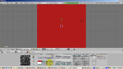
Position the camera directly at the plane with View - Align View - Align Active Camera to View.
Go to Front View (Num1). Press the Home key to see all the objects, particularly, the camera. Duplicate the plane (Shift-D). Move the plane upwards, in the Z direction (press the G key and then the Z key), so that it is behind the camera. The duplicated plane has Ray Mirror on as well.
Go to the Scene buttons (F10). Make sure the Ray button is turned on, so that Ray Tracing is enabled.
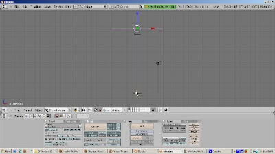
Center the 3D cursor by pressing Shift-C. Add the monkey (Space - Add - Mesh - Monkey). Add a new material by pressing F5 (Shaders) and clicking the Add New button. Make Suzanne green (R=0, G=1, B=0). Move the monkey 1 blender unit to the right and up a bit. Go to Edit buttons (F9). Press the Set Smooth button. Add a Subsurf Level 2, Render Level 3.
Make sure you are in Object Mode. If not, press the tab key. Add a UV Sphere (Space - Add - Mesh - UVSphere). Give the UV Sphere a blue color by going to the Shaders panel (F5), adding a new material (Add New button) and setting R=0, G=0, and B=1. Move the UV Sphere 2 blender units to the left and up a bit, off the floor of the plane. Press F9 to go to the Edit buttons. Click the Set Smooth button to smooth out the UV Sphere.
Press F12 to render. The red mirror should show the mirroring of both the monkey and the UV Sphere, as the light bounces off the bottom mirror, sees the monkey and the UV Sphere, and then the objects are mirrored off the top mirror. The shadow obscures somewhat the mirrored effect.
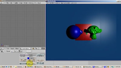
Let's turn off shadows. Go to the Scene buttons (F10) and click off Shadow. Press F12 to render. Now you get the effect of both the top mirror and the bottom mirror.
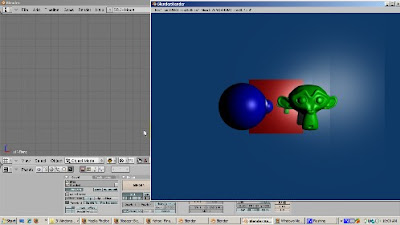
The mirror effect can be combined with the color effect. Select either mirror plane (Right click). Press F5 to access the Shaders buttons. In the Ray Mirror group, turn Ray Mirror to 0. Press F12 to render. There is no mirror effect. The monkey and the UV Sphere both render, and the plane is red.
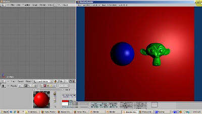
Now set Ray Mirror to .5, so we get half mirror and half color. Press F12 to render. Now the red base color shows through, but the mirror effect shows through as well. You can play with Ray Mirror to get the combination you like.
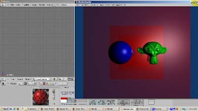
The mirror color can also play a role. Turn Ray Mirror back to 1 so we get the full ray mirror effect. Now let's set the mirror color to yellow. Select the Mirror color rectangle, and change it to Yellow (R=1, G=1, B=0). Press F12 to render. We get a really interestng result. The yellow mirror color mixes with the material's color. The monkey is green. Yellow already has green. So the mirrored monkey remains green. However, the sphere is blue. The mirror color, yellow, has no blue, so the mirrored UV sphere is yellow. By the way, there's also a blending with the sky color, which is also mirrored, which accounts for the color variation outside the mirror boundary.
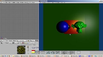
The Depth setting controls how many times the mirror effect bouncing is produced. Let's crank up the depth to 5 and press F12 to render. There are now more mirrored monkeys and UV Spheres.
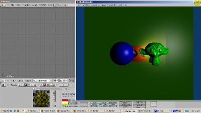
The Fresnel setting produces another interesting effect, mixing the mirror color, and the mirror's diffuse color. Let's crank Fresnel to 1.5 and render.
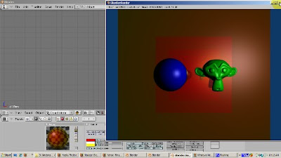
The Glossiness setting affects the blurriness of the reflection. The default of 100% glossiness produces a crisp reflection. A little bit of reduction goes a long way in increasing the realism of the render. Set glossiness to .9 (90%) and you'll get an effect that simulates a bit of dirt in the mirror.
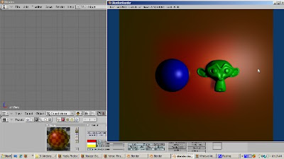
There's more. How about turning on Ray Mirror for the monkey and the UV Sphere. Select the monkey. Go to the Shading buttons (F5). Click the Ray Mirror button. Turn RayMir to 1. Then select the UVSphere, go to the shading buttons, and turn on Ray Mirror, setting it to 1. Press F12 to render. How about changing the mirror's shape? Subdivide the plane, rotate a few vertices, and render. I'll leave that to you.
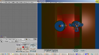
As you can see, there are a lot of neat effects you can achieve with Ray Mirror. I hope you have the basis for experimenting more and getting the effect you desire. Happy Blendering!
Ray tracing casts simulated rays of light on the scene and is on by default in Blender 2.49. Ray tracing gives the most realistic light properties in Blender, but the renders take the longest. That is why all of my renders in this video will be time lapsed. Don't expect the same rendering times as you see in this video, unless you work for Pixar or the Defense Department. For many animation and game engine applications, ray tracing rendering times are unacceptably slow. In other videos, we will discover alternatives, such as Z buffering, for which response times are more acceptable. However, the effects won't be as realistic as with ray mirror. In this video, we will be looking at a special type of ray tracing effect, ray mirror, which creates mirror reflections.
When a ray of light hits the surface of an object, one of three things can happen. The light can be absorbed by the object, the light can pass through the object (if the object has some transparency), or the light can be reflected back, which is what happens with a mirror. In reality, most objects have a combination of absorption, transparency, and reflective properties. Think of a blue light bulb. The light bulb looks blue because some of the light is absorbed by the material, glass or otherwise, to make it look blue. Perhaps you can see part of the inside of the light bulb, say if it is not frosted, such as the filament. That's because the light bulb has some transparent properties. Finally, if you can see part of the background through the light bulb, that's because of its mirror like, reflective properties. Ray Mirror controls this last property.
To show how Ray Mirror works, start up Blender and delete the default cube. Select the cube, press the Delete key and press Enter to confirm. Make sure you are in Top View by pressing Num7. Add a plane (Space - Add - Mesh - Plane). Scale the plane 5 times (S - 5 - Enter). The plane is going to act as a mirror. To make this happen, with the full Ray Mirror effect, press the Shading buttons (F5) and use the default material (Material). Click the Mirror Trans tab, then click the Ray Mirror button, and turn RayMir to 1. RayMir is a slider which goes from 0 to 1, representing 0% to 100% as a decimal number. Give the plane a red color (R=1, G=0, B=0).

Position the camera directly at the plane with View - Align View - Align Active Camera to View.
Go to Front View (Num1). Press the Home key to see all the objects, particularly, the camera. Duplicate the plane (Shift-D). Move the plane upwards, in the Z direction (press the G key and then the Z key), so that it is behind the camera. The duplicated plane has Ray Mirror on as well.
Go to the Scene buttons (F10). Make sure the Ray button is turned on, so that Ray Tracing is enabled.

Center the 3D cursor by pressing Shift-C. Add the monkey (Space - Add - Mesh - Monkey). Add a new material by pressing F5 (Shaders) and clicking the Add New button. Make Suzanne green (R=0, G=1, B=0). Move the monkey 1 blender unit to the right and up a bit. Go to Edit buttons (F9). Press the Set Smooth button. Add a Subsurf Level 2, Render Level 3.
Make sure you are in Object Mode. If not, press the tab key. Add a UV Sphere (Space - Add - Mesh - UVSphere). Give the UV Sphere a blue color by going to the Shaders panel (F5), adding a new material (Add New button) and setting R=0, G=0, and B=1. Move the UV Sphere 2 blender units to the left and up a bit, off the floor of the plane. Press F9 to go to the Edit buttons. Click the Set Smooth button to smooth out the UV Sphere.
Press F12 to render. The red mirror should show the mirroring of both the monkey and the UV Sphere, as the light bounces off the bottom mirror, sees the monkey and the UV Sphere, and then the objects are mirrored off the top mirror. The shadow obscures somewhat the mirrored effect.

Let's turn off shadows. Go to the Scene buttons (F10) and click off Shadow. Press F12 to render. Now you get the effect of both the top mirror and the bottom mirror.

The mirror effect can be combined with the color effect. Select either mirror plane (Right click). Press F5 to access the Shaders buttons. In the Ray Mirror group, turn Ray Mirror to 0. Press F12 to render. There is no mirror effect. The monkey and the UV Sphere both render, and the plane is red.

Now set Ray Mirror to .5, so we get half mirror and half color. Press F12 to render. Now the red base color shows through, but the mirror effect shows through as well. You can play with Ray Mirror to get the combination you like.

The mirror color can also play a role. Turn Ray Mirror back to 1 so we get the full ray mirror effect. Now let's set the mirror color to yellow. Select the Mirror color rectangle, and change it to Yellow (R=1, G=1, B=0). Press F12 to render. We get a really interestng result. The yellow mirror color mixes with the material's color. The monkey is green. Yellow already has green. So the mirrored monkey remains green. However, the sphere is blue. The mirror color, yellow, has no blue, so the mirrored UV sphere is yellow. By the way, there's also a blending with the sky color, which is also mirrored, which accounts for the color variation outside the mirror boundary.

The Depth setting controls how many times the mirror effect bouncing is produced. Let's crank up the depth to 5 and press F12 to render. There are now more mirrored monkeys and UV Spheres.

The Fresnel setting produces another interesting effect, mixing the mirror color, and the mirror's diffuse color. Let's crank Fresnel to 1.5 and render.

The Glossiness setting affects the blurriness of the reflection. The default of 100% glossiness produces a crisp reflection. A little bit of reduction goes a long way in increasing the realism of the render. Set glossiness to .9 (90%) and you'll get an effect that simulates a bit of dirt in the mirror.

There's more. How about turning on Ray Mirror for the monkey and the UV Sphere. Select the monkey. Go to the Shading buttons (F5). Click the Ray Mirror button. Turn RayMir to 1. Then select the UVSphere, go to the shading buttons, and turn on Ray Mirror, setting it to 1. Press F12 to render. How about changing the mirror's shape? Subdivide the plane, rotate a few vertices, and render. I'll leave that to you.

As you can see, there are a lot of neat effects you can achieve with Ray Mirror. I hope you have the basis for experimenting more and getting the effect you desire. Happy Blendering!
Tuesday, December 8, 2009
Multiple Materials
Join my Blender 3D forum, where you can network with other Blender friends and get your Blender 3D questions answered.
Many times you will be assigning one material to an entire object. However, there are situations where you want to assign different parts of an object to their own material. The assignment can get kind of tricky. In this demo, we will make each face of a cube have a different colored material. You can then extend this to customize each material, such as changing its opacity or transparency, on each face. You can also add separate textures to each material. This tutorial shows you how to do the first step: creating a separate material for each face of a cube.
Steps:
1) We'll start with the default 2.49b scene and use the default cube. Press Tab to go to Edit mode. Go to Face Select mode (Control - Tab - 3 or the triangle icon. Press A to deselect all faces. Rotate the cube on its side, to make selecting a face easier. Press Z to go to wireframe mode.
Materials are assigned per face. Each face can have only 1 material ID. New materials are given the next material ID, 2 for the second one, 3 for the third one, and so on. A set of buttons in Edit (F9( assigns multiple material IDs. By default, when you Add New material, all faces have a Material ID 1. Press F5 for the shading buttons. There's an indicator (1 Mat 1) that shows how many materials are on the object (1), and which one we're working on (1).
2) Create 5 new materials. By default, each face of the cube has a material, called Material, assigned to it. The Material button group shows that there is 1 material assigned to the cube. Press F9 to get to the Editing buttons. Press the New key 5 times. Now there are 6 materials, with the names Material, Material.001, Material.002, all the way to Material.005.
3) Assign the faces to their respective materials:
Go to F9 (Editing buttons). Assign the faces as follows:
Select the top face. Set its material to Material (ID = 1). Click Assign.
Select the bottom face. Set its material to Material.001 (ID = 2). Click Assign.
Select the left face. Set its material to Material.002 (ID = 3) Click Assign.
Select the right face. Set its material to Material.003 (ID=4). Click Assign.
Select the front face. Set its material to Material.004 (ID = 5). Click Assign.
Select the back face. Set its material to Material.005 (ID=6). Click Assign.
You can verify which material is associated with which face. Press the A key to deselect all faces. Select a material, say Material.004. Click the Select button and you should see that the material is assigned to the top face. You can also do the opposite. Press A to deselect all faces. Click the bottom face. Click the question mark icon. You should see that Material.001, with material ID 2, is assigned.
4) Click F5 to go to the Shading buttons. We want our materials to have meaningful names so we can identify them easily. Assign the following colors:
Material: Red (R=1, G=0, B=0). Press Autoname to have Blender create a meaningful name (Red).
Material.001: Green (R=0, G=1, B=0). Press Autoname. Blender calls this LightGreen.
Material.002: Blue (R=0, G=0, B=1). Press Autoname. Blender calls this LightBlue.
Material.003: Yellow (R=1, G=1, B=0). Press Autoname. Blender calls this material Yellow.
Material.004: Magenta (R=1, G=0, B=1). Press Autoname. Blender calls this material Magenta.
Material.005: Cyan (R=0, G=1, B=1). Press Autoname. Blender calls this material Cyan.
To view our result, press Tab to go into Object mode. Then go into Shaded mode. Rotate the cube. Press F12 to render.
You can further refine this by changing the characteristics of a material by playing with settings such as Ray Mirror, Alpha, Ray Transparency, the render pipeline, and so on. You can produce some interesting effects. Happy Blendering.
Many times you will be assigning one material to an entire object. However, there are situations where you want to assign different parts of an object to their own material. The assignment can get kind of tricky. In this demo, we will make each face of a cube have a different colored material. You can then extend this to customize each material, such as changing its opacity or transparency, on each face. You can also add separate textures to each material. This tutorial shows you how to do the first step: creating a separate material for each face of a cube.
Steps:
1) We'll start with the default 2.49b scene and use the default cube. Press Tab to go to Edit mode. Go to Face Select mode (Control - Tab - 3 or the triangle icon. Press A to deselect all faces. Rotate the cube on its side, to make selecting a face easier. Press Z to go to wireframe mode.
Materials are assigned per face. Each face can have only 1 material ID. New materials are given the next material ID, 2 for the second one, 3 for the third one, and so on. A set of buttons in Edit (F9( assigns multiple material IDs. By default, when you Add New material, all faces have a Material ID 1. Press F5 for the shading buttons. There's an indicator (1 Mat 1) that shows how many materials are on the object (1), and which one we're working on (1).
2) Create 5 new materials. By default, each face of the cube has a material, called Material, assigned to it. The Material button group shows that there is 1 material assigned to the cube. Press F9 to get to the Editing buttons. Press the New key 5 times. Now there are 6 materials, with the names Material, Material.001, Material.002, all the way to Material.005.
3) Assign the faces to their respective materials:
Go to F9 (Editing buttons). Assign the faces as follows:
Select the top face. Set its material to Material (ID = 1). Click Assign.
Select the bottom face. Set its material to Material.001 (ID = 2). Click Assign.
Select the left face. Set its material to Material.002 (ID = 3) Click Assign.
Select the right face. Set its material to Material.003 (ID=4). Click Assign.
Select the front face. Set its material to Material.004 (ID = 5). Click Assign.
Select the back face. Set its material to Material.005 (ID=6). Click Assign.
You can verify which material is associated with which face. Press the A key to deselect all faces. Select a material, say Material.004. Click the Select button and you should see that the material is assigned to the top face. You can also do the opposite. Press A to deselect all faces. Click the bottom face. Click the question mark icon. You should see that Material.001, with material ID 2, is assigned.
4) Click F5 to go to the Shading buttons. We want our materials to have meaningful names so we can identify them easily. Assign the following colors:
Material: Red (R=1, G=0, B=0). Press Autoname to have Blender create a meaningful name (Red).
Material.001: Green (R=0, G=1, B=0). Press Autoname. Blender calls this LightGreen.
Material.002: Blue (R=0, G=0, B=1). Press Autoname. Blender calls this LightBlue.
Material.003: Yellow (R=1, G=1, B=0). Press Autoname. Blender calls this material Yellow.
Material.004: Magenta (R=1, G=0, B=1). Press Autoname. Blender calls this material Magenta.
Material.005: Cyan (R=0, G=1, B=1). Press Autoname. Blender calls this material Cyan.
To view our result, press Tab to go into Object mode. Then go into Shaded mode. Rotate the cube. Press F12 to render.
You can further refine this by changing the characteristics of a material by playing with settings such as Ray Mirror, Alpha, Ray Transparency, the render pipeline, and so on. You can produce some interesting effects. Happy Blendering.
Sunday, December 6, 2009
Rip Tool
Join my Blender 3D forum, where you can network with other Blender friends and get your Blender 3D questions answered.
The Rip tool lets you tear out a hole, such as a mouth or an eye socket if you're modeling a face, in your mesh. You can use the Rip Tool in either vertex select or edge select mode. The Rip Tool does not work in Face Select Mode. You can also use the Rip tool to do split apart a mesh, for example, splitting a sphere into two halves. You can create faces to join the parts of the mesh that you have ripped. The goal of this tutorial is to make you comfortable both ripping a mesh apart to create holes where you want them, and to join mesh parts together again.
We'll start with the default Blender 2.49b scene. Delete the default cube (press the Delete key and press Enter to confirm). Add a plane (Space - Add - Mesh - Plane). The plane is in Object mmode. Scale the plane to 4 times its original size (S - 4 - Enter). Get rid of the 3D Transform Manipulator to make the demonstration of the Rip Tool easier to follow.
Press Tab to go into Edit mode. Press the Edit buttons (F9) and click the Subdivide button 3 times. Press the A key to deselect all vertices.
Look at the indicators for vertices, edges, and faces. Right now, the plane has 81 vertices, 144 edges, and 64 faces. The zeroes show that nothing is selected.
Make sure you are in Vertex Select Mode (Control - Tab - 1) or the Vertex Select icon. Position the 3D cursor below and to the right of the vertex you want to select. Select the vertex, then press the V key, grabbing the vertex to the right. A hole is created to the right of the vertex. Look at the indicators for vertices, edges, and faces. Before the plane had 81 vertices, of which none were selected. Now, the plane has 82 vertices, and one is selected.
This gives a clue as to what the Rip tool actually does. It creates a duplicate vertex at the same spot as the selected vertex, connected to the vertices as the copied vertex. When the mesh is ripped, that vertex drags the adjacent edges with it. The 3D cursor position determines the direction of the rip.
Press Alt-U, which brings up the Undo History. Click on Select to undo the rip. Now we're back to having the vertex selected, with 81 vertices altgether. Move the cursor above and to the left of the selected vertex. You can constrain the rip to an axis. To do that, press the V key, and then the Y key to constrain the rip to the Y axis. Press Enter to confirm. So you can see that the direction of the rip depends on the position of the 3D cursor at the time that you press the V key. The rip is along the edge that is closest to the selected vertex.
Press the A key to deselect the vertex. Go to another part of the plane, and select a vertex. Then Shift select (Shift - Right Click) the vertex immediately to the right of it. Position the 3D cursor above and in the middle of the selected vertices. Press the V key. You now get a bigger rip, a trapezoid, with 2 vertices on top and 4 vertices on the bottom. So a rip with N selected vertices produces a ripped polygon with N vertices in the ripped direction and N+2 vertices in the original direction.
If you start the Rip and then immediately decide not to continue, the new vertices still remain. To illustrate this, select a vertex, press the V key, and then press Esc. The vertex created by the Rip tool is still there. You can rip the mesh now even though you pressed Esc. Press the G key and move the vertex and the mesh is ripped. Press Enter to confirm.
Press the A key to deselect all vertices. Suppose you want to patch up the hole that you created. The solution is to select the vertices for the new face (3 or 4) and press the F key. To illustrate this, select the 4 vertices that form the square of the hole created from 2 selected vertices. Press the F key. A face is created.
Press the A key to deselect all vertices. Now we'll create triangular faces for the remaining two holes. Select the 3 vertices forming the left triangle, and press F. Press the A key to deselect everything. Select the 3 vertices forming the right triangle, and press F. The hole is now repaired. Press the A key to deselect.
Ripping via an edge loop is a great way to split a mesh. Select an Edge Loop by positioning the 3D cursor on an edge and pressing Alt-Right Click. Then press the V key and scroll down. Press Enter to confirm. You have now split the mesh along the edge loop.
Rip works in edge mode as well. Go into Edge mode, by either selecting the Edge icon or pressing Control - Tab - 2. Position the 3D cursor above an edge to select. Select the edge (Right Click on an edge). Press the V key. The rip works just like selecting two adjacent vertices, which is, of course, what constitutes an edge.
Press the A key to deselect everything. You rip on two edges along the same loop. Select an unselected edge. Then Shift Select (right click while holding the Shift key) to select the edge next to it. Press the V key. The rip works in the trapezoidal fashion you would expect.
Rip works on other meshes as well. Let's look at a UV Sphere. Press tab to go to object mode. Click the second square to go to Level 2, so we have a blank 3D viewport. Add a UV Sphere (Space - Add - Mesh -UVSphere), accepting the default of 32 rings and 32 segments. Press Z to go into wireframe mode. Scale the UVSphere 3 times (S - 3 - Enter). Press Tab to go into Edit mode. Go into Edge select mode (Control - Tab - 2). Press the A key to deselect everything.
Press Num 1 key to go to front view. Position the cursor on an edge and press Alt-Right Click to select an edge loop. Position the 3D cursor below the selected loop. Press the V key. Move the selected edge loop down. Behold, you have split the UV Sphere. Press Z to go into solid mode so you can see.
Ycu can also rip and scale at the same time. Select another edge loop (Alt- Right Click) for splitting the UV Sphere. Position the 3D cursor below the loop. Press the V key, then the Z key to constrain along the Z axis, drag the edge down. Press Enter. Then press the S key to scale the loop.
I hope this gives you a good idea of the Rip tool, which is very handy for creating holes in a mesh. Happy Blendering!
The Rip tool lets you tear out a hole, such as a mouth or an eye socket if you're modeling a face, in your mesh. You can use the Rip Tool in either vertex select or edge select mode. The Rip Tool does not work in Face Select Mode. You can also use the Rip tool to do split apart a mesh, for example, splitting a sphere into two halves. You can create faces to join the parts of the mesh that you have ripped. The goal of this tutorial is to make you comfortable both ripping a mesh apart to create holes where you want them, and to join mesh parts together again.
We'll start with the default Blender 2.49b scene. Delete the default cube (press the Delete key and press Enter to confirm). Add a plane (Space - Add - Mesh - Plane). The plane is in Object mmode. Scale the plane to 4 times its original size (S - 4 - Enter). Get rid of the 3D Transform Manipulator to make the demonstration of the Rip Tool easier to follow.
Press Tab to go into Edit mode. Press the Edit buttons (F9) and click the Subdivide button 3 times. Press the A key to deselect all vertices.
Look at the indicators for vertices, edges, and faces. Right now, the plane has 81 vertices, 144 edges, and 64 faces. The zeroes show that nothing is selected.
Make sure you are in Vertex Select Mode (Control - Tab - 1) or the Vertex Select icon. Position the 3D cursor below and to the right of the vertex you want to select. Select the vertex, then press the V key, grabbing the vertex to the right. A hole is created to the right of the vertex. Look at the indicators for vertices, edges, and faces. Before the plane had 81 vertices, of which none were selected. Now, the plane has 82 vertices, and one is selected.
This gives a clue as to what the Rip tool actually does. It creates a duplicate vertex at the same spot as the selected vertex, connected to the vertices as the copied vertex. When the mesh is ripped, that vertex drags the adjacent edges with it. The 3D cursor position determines the direction of the rip.
Press Alt-U, which brings up the Undo History. Click on Select to undo the rip. Now we're back to having the vertex selected, with 81 vertices altgether. Move the cursor above and to the left of the selected vertex. You can constrain the rip to an axis. To do that, press the V key, and then the Y key to constrain the rip to the Y axis. Press Enter to confirm. So you can see that the direction of the rip depends on the position of the 3D cursor at the time that you press the V key. The rip is along the edge that is closest to the selected vertex.
Press the A key to deselect the vertex. Go to another part of the plane, and select a vertex. Then Shift select (Shift - Right Click) the vertex immediately to the right of it. Position the 3D cursor above and in the middle of the selected vertices. Press the V key. You now get a bigger rip, a trapezoid, with 2 vertices on top and 4 vertices on the bottom. So a rip with N selected vertices produces a ripped polygon with N vertices in the ripped direction and N+2 vertices in the original direction.
If you start the Rip and then immediately decide not to continue, the new vertices still remain. To illustrate this, select a vertex, press the V key, and then press Esc. The vertex created by the Rip tool is still there. You can rip the mesh now even though you pressed Esc. Press the G key and move the vertex and the mesh is ripped. Press Enter to confirm.
Press the A key to deselect all vertices. Suppose you want to patch up the hole that you created. The solution is to select the vertices for the new face (3 or 4) and press the F key. To illustrate this, select the 4 vertices that form the square of the hole created from 2 selected vertices. Press the F key. A face is created.
Press the A key to deselect all vertices. Now we'll create triangular faces for the remaining two holes. Select the 3 vertices forming the left triangle, and press F. Press the A key to deselect everything. Select the 3 vertices forming the right triangle, and press F. The hole is now repaired. Press the A key to deselect.
Ripping via an edge loop is a great way to split a mesh. Select an Edge Loop by positioning the 3D cursor on an edge and pressing Alt-Right Click. Then press the V key and scroll down. Press Enter to confirm. You have now split the mesh along the edge loop.
Rip works in edge mode as well. Go into Edge mode, by either selecting the Edge icon or pressing Control - Tab - 2. Position the 3D cursor above an edge to select. Select the edge (Right Click on an edge). Press the V key. The rip works just like selecting two adjacent vertices, which is, of course, what constitutes an edge.
Press the A key to deselect everything. You rip on two edges along the same loop. Select an unselected edge. Then Shift Select (right click while holding the Shift key) to select the edge next to it. Press the V key. The rip works in the trapezoidal fashion you would expect.
Rip works on other meshes as well. Let's look at a UV Sphere. Press tab to go to object mode. Click the second square to go to Level 2, so we have a blank 3D viewport. Add a UV Sphere (Space - Add - Mesh -UVSphere), accepting the default of 32 rings and 32 segments. Press Z to go into wireframe mode. Scale the UVSphere 3 times (S - 3 - Enter). Press Tab to go into Edit mode. Go into Edge select mode (Control - Tab - 2). Press the A key to deselect everything.
Press Num 1 key to go to front view. Position the cursor on an edge and press Alt-Right Click to select an edge loop. Position the 3D cursor below the selected loop. Press the V key. Move the selected edge loop down. Behold, you have split the UV Sphere. Press Z to go into solid mode so you can see.
Ycu can also rip and scale at the same time. Select another edge loop (Alt- Right Click) for splitting the UV Sphere. Position the 3D cursor below the loop. Press the V key, then the Z key to constrain along the Z axis, drag the edge down. Press Enter. Then press the S key to scale the loop.
I hope this gives you a good idea of the Rip tool, which is very handy for creating holes in a mesh. Happy Blendering!
Thursday, November 12, 2009
2.49b Depth of Field Nodes
Join my Blender 3D forum, where you can network with other Blender friends and get your Blender 3D questions answered.
Hi. The eye naturally focuses on sharper objects in a scene and tends to overlook blurred objects. Depth of Field (DOF) is a technique in which you highlight objects in focus, giving them the illusion of being closer to the camera, and blur out the parts of the scene that are not as important. You can use this to force your viewers to focus on the objects you consider important. Using Blender's composite nodes, with some mathematical trickery, you can set up Depth of Field.
So let's get started. Fire up Blender, delete the default cube (Right Click, Delete key, and Enter to confirm). Add the monkey mesh (Space - Add - Mesh - Monkey). Let's make the monkey green. Press F5 (Shading). Then click Add New to add a new material. Set R=0, G=1, and B=0. Go to the Edit buttons (F9). Press the Set Smooth button to make Suzanne more presentable.
Let's make more Suzannes. Click the Modifier button, at the extreme right. Add an Array Modifier. Make sure Relative Offset is clicked. Set X= -1, Y=0, and Z=0. Set Count = 8. Press F12 to render. We now have 8 monkeys, each a bit farther away from the camera than the previous one. The last two monkeys are out of camera range. To fix this, press N to bring up the Transform Properties window. Set LocX to 3. Now there are 8 monkeys in camera range.
Suppose we want our viewers to focus on the first monkey and gradually blur the rest of them as they get further from the camera. We can achieve this effect with Composite Nodes. To do this, change the window type of the 3D Viewport to Node Editor. We start out with two nodes. The input Render Layers node is our original scene before the composite node magic is applied. The output Composite node is the final, composited result. Move the Composite node all the way to the right.
Add a Map Value node (Space - Add - Vector - Map Value). Map Value takes information and maps it into a range of values. Map Value can also add a number (the Offset), as well as multiply by a number (the Scale) from the input. We're going to play with the offset and scale in a minute. In this case, we are going to map the Z value, which is the distance, in Blender Units, of each pixel, from the camera. Connect the Z socket of the Render Layers node to the Value socket of the Map Value node.
Next, add a Color Ramp node (Space - Add - Converter - ColorRamp). The color ramp gives us a visual representation of the Z values, with values from 0 (black) to 1 (white), Connect the Map Value's Value socket to the Factor socket of the Color Ramp node. Then, connect the ColorRamp image socket to the Composite Node image socket.
Right now the compositor shows all white. That's because all the monkeys map to a value of 1 or greater. The first monkey is about 5 Blender Units from the camera. With this mapping, the monkeys all map to white.
However, if we adjust the offset to -6 and the Size to .1, we get an interesting falloff from black to white. What happens is that for distances between 6 and 16 Blender units, we map a value between 0 and 1. Here's an example. Take a pixel at 10 Blender Units from the camera. First subtract 6, to get 4, then multiply 4 by .1, yielding a value of .4, which maps to a grayish color 40% between black and white. Any Z distance less than 6 produces black. A value greater than 16 produces white. We can translate this falloff into a gradual blurring.
To do this, add a Blur node (Space - Add - Filter - Blur). Connect the Image socket of the Render Layer node to the Image socket of the Blur node. That will feed the original scene to the blur node. Then, connect the Image socket of the ColorRamp node to the Size socket of the Blur node, feeding the adjusted Z values to the Blur node. Connect the Image socket of the Blur node to the Image socket of the Composite node.
You need to fiddle around with the X and Y values in the blur node to set up the exact amount of blur falloff. I found that X=6 and Y=6 worked well for focusing on the first monkey and gradually fading out the others.
We're ready to render. Go to the scene buttons (F10). Press the Do Composite button to tell the Renderer that we are using composite nodes. Press F12 to render. You should get the depth of field effect we're aiming for.
That's it. I hope this gives you some interesting ideas for highlighting objects in your scene using depth of field. Happy Blendering!
Hi. The eye naturally focuses on sharper objects in a scene and tends to overlook blurred objects. Depth of Field (DOF) is a technique in which you highlight objects in focus, giving them the illusion of being closer to the camera, and blur out the parts of the scene that are not as important. You can use this to force your viewers to focus on the objects you consider important. Using Blender's composite nodes, with some mathematical trickery, you can set up Depth of Field.
So let's get started. Fire up Blender, delete the default cube (Right Click, Delete key, and Enter to confirm). Add the monkey mesh (Space - Add - Mesh - Monkey). Let's make the monkey green. Press F5 (Shading). Then click Add New to add a new material. Set R=0, G=1, and B=0. Go to the Edit buttons (F9). Press the Set Smooth button to make Suzanne more presentable.
Let's make more Suzannes. Click the Modifier button, at the extreme right. Add an Array Modifier. Make sure Relative Offset is clicked. Set X= -1, Y=0, and Z=0. Set Count = 8. Press F12 to render. We now have 8 monkeys, each a bit farther away from the camera than the previous one. The last two monkeys are out of camera range. To fix this, press N to bring up the Transform Properties window. Set LocX to 3. Now there are 8 monkeys in camera range.
Suppose we want our viewers to focus on the first monkey and gradually blur the rest of them as they get further from the camera. We can achieve this effect with Composite Nodes. To do this, change the window type of the 3D Viewport to Node Editor. We start out with two nodes. The input Render Layers node is our original scene before the composite node magic is applied. The output Composite node is the final, composited result. Move the Composite node all the way to the right.
Add a Map Value node (Space - Add - Vector - Map Value). Map Value takes information and maps it into a range of values. Map Value can also add a number (the Offset), as well as multiply by a number (the Scale) from the input. We're going to play with the offset and scale in a minute. In this case, we are going to map the Z value, which is the distance, in Blender Units, of each pixel, from the camera. Connect the Z socket of the Render Layers node to the Value socket of the Map Value node.
Next, add a Color Ramp node (Space - Add - Converter - ColorRamp). The color ramp gives us a visual representation of the Z values, with values from 0 (black) to 1 (white), Connect the Map Value's Value socket to the Factor socket of the Color Ramp node. Then, connect the ColorRamp image socket to the Composite Node image socket.
Right now the compositor shows all white. That's because all the monkeys map to a value of 1 or greater. The first monkey is about 5 Blender Units from the camera. With this mapping, the monkeys all map to white.
However, if we adjust the offset to -6 and the Size to .1, we get an interesting falloff from black to white. What happens is that for distances between 6 and 16 Blender units, we map a value between 0 and 1. Here's an example. Take a pixel at 10 Blender Units from the camera. First subtract 6, to get 4, then multiply 4 by .1, yielding a value of .4, which maps to a grayish color 40% between black and white. Any Z distance less than 6 produces black. A value greater than 16 produces white. We can translate this falloff into a gradual blurring.
To do this, add a Blur node (Space - Add - Filter - Blur). Connect the Image socket of the Render Layer node to the Image socket of the Blur node. That will feed the original scene to the blur node. Then, connect the Image socket of the ColorRamp node to the Size socket of the Blur node, feeding the adjusted Z values to the Blur node. Connect the Image socket of the Blur node to the Image socket of the Composite node.
You need to fiddle around with the X and Y values in the blur node to set up the exact amount of blur falloff. I found that X=6 and Y=6 worked well for focusing on the first monkey and gradually fading out the others.
We're ready to render. Go to the scene buttons (F10). Press the Do Composite button to tell the Renderer that we are using composite nodes. Press F12 to render. You should get the depth of field effect we're aiming for.
That's it. I hope this gives you some interesting ideas for highlighting objects in your scene using depth of field. Happy Blendering!
Wednesday, October 28, 2009
2.49b Particle Objects
Blender's particle system is flexible and powerful. It can be used for simulating effects like fire, hair, fur, rain. Particles can be emitted from any kind of mesh object. The purpose of this video is to acquaint you with the basic controls for a particle emitter. We'll use the plane, which is the simplest to show. Switch to animation view, with 100 frames.
1) Delete the default cube (Right click, then X, then confirm delete). Add a plane (Space - Add - Mesh - Plane). Subdivide the plane once (W key, then subdivide). Then go to the SR1-Animation view.
2) Go to the Object buttons (F7), then click the Particles button, all the way to the right. We will look at emitter type particles, where the number of particles and their direction change over time. Emitters are good for animating rain and fire, where raindrops and smoke particles move over time. The hair type is for more static simulations, like hair and fur.
3) Particles are emitted from faces of the plane. The default is 1000 particles over 100 frames = 10 particles per frame.
4) Increase the number of particles to 10000. You see that they're emitting from each face by default. Can change to emit from vertices, as well as volume.
5) Particles are most often emitted from the "normals", the direction that's perpendicular from the face. The Normals setting controls how high the particles are emitted. Set the normal to 1 to show how height is controlled. Press F12 to render.
6) Random adds a bit of randomness to the emitting direction. You can mix normals and random and press F12 to rendeer.
7) AccX, AccY, and AccZ can add an extra push in the respective direction. Set AccX to .5, which gives bias in the X direction of .5 blender units. This is good for fire and smoke effects. Press Alt-A to see the path of the animation.
8) Emitting also works in negative direction. For rain, if you float a plane above the scene, and make it a particle emitter, this would be the start of a rain simulation. You can increase the randomness as well. Set Normals to -.5 and AccX to -.3. Properly textured, this could simulate a heavy rainstorm.
9) Start and End are the start and end frames for the particles. Life is how long the particle lives. Increasing the life makes the particles stay around longer. Start can be negative, which means that the particles are alive at the beginning of the animation.
Increase the life to 100. The particles stay around longer. For fireworks, you might want to vary the life and add some randomness to the emitter.
10) Start can be a negative number also. A negative start number means the simulation began before the first frame is rendered, like the fire is already going at frame 1.
11) Go to a frame 41 and press F12 to render. The particles render as halos, and the plane does not render. The emitter does not render by default.
12) Add a material, F5, shading, make the particles red (R=1, G=0, and B=0). Then press F12 render.
13) To change the halo effects, press the Halo button in the Render Pipeline panel. In the Shaders panel, you can change the halo size. You can also customize the halo - Rings, lines, stars.
Render (F12) for
1) Halo with 4 rings and .5 size.
2) Halo with size .1, 3 stars, and 4 lines
14) Many material settings can be animated. Look at Halo Size. Go to IPO window. Select the Material type curves. Then select HaSize. Create an IPO curve, with Control-Left Click, creating IPO points for size. This creates a Bezier curve for the halo size, which will make them emit with different sizes over time. Here's the resulting video.
These are the basic controls and look for emitter type particles, which work well for fire and rain. We've barely scratched the surface. I hope this gives you a good start towards understanding Blender's partcle system. Happy blending!
Friday, October 23, 2009
2.49b Fluid Simulation
The purpose of this video is to show how the objects in Blender's fluid simulator work. We'll look at domains, obstacles, inflow, outflow, and of course fluid objects. Blender's fluid simulator at first seems very challenging. However, if you think about how fluids behave in real life - think of water pouring out of a faucet into a sink or a bathtub, the fluid simulator starts to become more logical. In this tutorial we're going to focus on the objects in Blender's fluid simulation.
Let's start with the most basic fluid simulation. At a minimum, the fluid simulator needs two things: a fluid, which can be free flowing like a waterfall or muddy like water in a pond; and a domain, which is an area in which the fluid lives. Be warned. This doesn't look exactly like water dripping from a faucet, but it does look like some icky gook falling down in a fluid like manner.
So start Blender. Usually we delete the default cube. This time, however, we will use the default cube. It will be the domain, the area in which the the fluid lives. Go to Front View, by pressing NUM1. The blue Z arrow will point up. We need this because fluids are affected by gravity. In Blender, Z is up and -Z is down.
Let's make the domain a bit higher along the z axis. Press the S key to scale, then the Z key, then scale the cube up 4 blender units. Grab it, with the G key, and move it along the Z direction (Z key) so the domain sits on the X axis. Before we do anything with the cube, duplicate it (Shift-D) and move it away from the original cube. You'll see later why this is a good idea.

Just to track things, let's name our objects. Select the original cube. Press the N key to bring up the Transform Properties window. Rename the cube to Domain. Make sure the cube is in object mode. Press Tab if the cube is in Edit mode.
To tell the fluid simulator that the cube is the domain, press the Object buttons (F7), then the Physics button, the second button in second group of buttons. Press the Fluid button the enable the fluid simulator, on the extreme right. Click the Domain button.

Press the Z key to go into wireframe mode. You can see objects inside of other objects in wireframe mode.
We need to add a fluid. Add an icosphere (Space - Add - Mesh - Icosphere), accepting the default of 2 subdivisions. Scale it down using the S key, so that the icosphere looks like a drop and is positioned at the top part of the cube. Make sure that the icosphere is inside the cube. Check out all the views and rotate, to make sure.
In the Transform Properties window, rename the icosphere from Sphere to Fluid. Let's make the fluid source green, just so we can see it. Press F5 to add a material. To make the fluid source green, set R to 0, G to 1, and B to 0.
Select the domain and go to the material buttons. Make the domain color red by setting R to 1, G to 0, and B to 0. Weird things happen to the domain during the fluid simulation, as you'll see.
To tell fluid simulator that the icosphere is the fluid, make sure the icosphere is in Object mode. Then press the Object buttons (F7) and the Physics button. Press the Fluid button to enable the fluid simulator. Click the Fluid button.

We're set up to run the fluid simulator. The cube is the domain and the icosphere is the fluid. To run it, select the cube. In the fluid simulator buttons for the cube, press the big BAKE button. The cube turns into a blob and starts falling down like a drop. The falling stops where the cube used to be, as if the cube was still there, although it doesn't show.
Believe it or not, we've created a fluid animation. Press Alt-A to see it. Press Esc to stop the animation. The animation is done over 250 frames by default. To create an animation, press F10 (Scene buttons). Set the Output Directory to the directory where you want to store the animation. In the Output panel, navigate to the directory and then select Select Output Pictures. In the Format panel, select the type of video you want to create. The default is jpeg. I like the .avi format, with the CamStudio 1.4 Lossless Codec. I use CamStudio to capture screen shots for these tutorials. If you choose uncompressed the video will take a lot of space. Click the ANIM button and wait. The animation is being created, all 250 frames of it.
Depending on your computer, the animation can take a long time, up to 10 minutes.
I paused the video because it's kind of boring to watch the animation being created frame by frame. Here's the result.
Some things to note. The fluid looks too geometric to be believable. We can help this by smoothing the fluid. Select the domain object, which controls the color of the fluid as it falls. Go to the edit buttons. Press the Set Smooth button. Also, subsurfing the fluid will help. Add a subsurf modifier at Level 2. Select the domain. Press the BAKE button. For the sake of speed, let's reduce the number of frames to 50. At 25 frames per second, this is a 2 second video, but it illustrates the point.
Select the Fluid object. Go to the Physics buttons and change its type from Fluid to Inflow. Here's the result.
The fluid is more, well, fluid-like. An inflow is a fluid object that adds fluid. Blender allows more than one fluid source, i.e. more than one inflow, like more than one faucet or shower head. However, only one domain is allowed.
We're going to add an obstacle. Add a cube below the path of the fluid. Select the cube, making sure it's in Object Mode. Click on the Object buttons, then the Physics buttons. Go to the Fluid simulator. Enable Fluid and click on Obstacle. Running the fluid simulator produces the following result.
Finally, we're going to add an outflow, which takes fluid away from the simulator. An outflow is like a bathtub or faucet drain. To do this, add a plane above the cube, in the path of the fluid. Select the plane, in object mode. Go to the Fluid simulator, as before. Enable Fluid and click the Outflow button. Select the domain and press the Bake button. The animation should look as shown, The fluid disappears before it hits the obstacle.
Remember the cube domain that we duplicated before? To make the simulation realistic, position it on the domain boundaries. You'll need to make it transparent and add materials and textures, no doubt. And probably you will want to apply a realistic water, oil, or mucky texture to your fluids. But that's it. We've done a basic fluid simulation, with a fluid and a domain. We've added an obstacle - in real life, something like a bathtub or sink, as well as an outflow, like a drain. I hope this gives you the basic idea of how it works. Happy Blending.
Monday, October 19, 2009
2.49b Realistic Bouncing Ball
Download the Bouncing Ball blend file
At first glance, one might think that animating a bouncing ball would be easy, a simple matter of moving a sphere and adding location keyframes. Sure, the ball would move. However, it would not bounce realistically. Because of gravity, the ball moves slower at the top than at the bottom. The ball actually is stretched a bit in the middle of the bounce and squashes when it hits the floor. Because of friction, the height of the next bounce is less than the height of the previous bounce. The spin of the ball must be realistic as well.
We're not going to address all these things. The purpose of this tutorial, which is based on the Blender 3D Noob To Pro bouncing ball tutorial, is to show the basics of animating a bouncing ball, including squashing the ball using lattice deformation and how to use IPO curves to bounce the ball a number of times without redoing the first bounce sequence again and again. I used Blender 2.49B.
We'll start by deleting the default cube (Right click, pressing the X key, and confirming the delete). Then add a UV Sphere (Space-Add-Mesh-UVSphere), accepting the default settings of 32 rings and 32 segments. From the editing buttons (F9), press Set Smooth. Then add a subsurf modifier at level 2. This gives us a nice round ball.
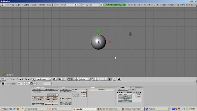
Press Num1 to go into Front View. Add a Lattice (Space-Add-Lattice). Press Z to go into wireframe mode. Select the lattice. Scale the lattice so that the UV Sphere is inside of it, with the sides of the lattice touching the sides of the sphere.
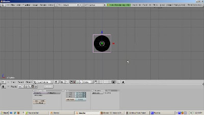
To make the lattice control the sphere, select the sphere, then Shift Select the lattice. Press Control-P and choose the Lattice Deform option to make the lattice the parent of the sphere. Select the UV Sphere and press F9. Look at the modifier stack. You should see the phrase "Lattice parent deform" at the top of the stack. This means that the lattice modifier was applied correctly. To test this, select the lattice and scale or move it. The sphere mesh should scale or move as well. We'll use the lattice later to squash the ball. The Make Real button would make the lattice permanently control the ball. We can ignore this button for this simple tutorial.
Now it's time to animate the ball. To do this, switch to Scene SR:1-Animation. This built in scene setup has all the windows we need for animation - the Outline Window, the 3D viewport of course, the IPO window, which we'll use later, and the buttons window.
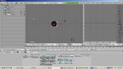
Position the 3D cursor in the 3D viewport and press Num1 to go to Front View. The blue Z arrow should point upwards. We're going to animate the first bounce over 23 frames, which is about 1 second assuming a standard movie speed of 24 frames per second. Press F10 to go to the Scene buttons, and set the end frame to 23.
It's time to insert key frames. Note that we are animating the lattice, not the ball.
Make sure we're in Frame 1. If not, press Shift-Left Arrow or enter the number 1 in the Frame Number area. We start the animation when the ball is at the top of its bounce. Press the G key, then the Z key, to move the lattice up in the Z direction, about 7 blender units or so, to the top of the bounce.
Press the I key and set a key for LocRotScale. Note how there are now 9 curves in the IPO window, for location, rotation, and scale, in the X, Y, and Z direction. You get 3 curves for each, for X, Y, and Z.
Go to Frame 11. Press the G key, then the Z key. Mgzove the lattice down in the Z direction, to 1 Blender unit above the ground. This is where the ball will be squashed a bit. Press the I key and insert a LocRotScale key.
Go to Frame 13. Leave the Lattice in the same position and insert another LocRotScale key.
Go to Frame 23. Move the Lattice back to its position at Frame 1 by pressing the G key, then the Z key, then moving it back to 7 Blender Units up. In real life, the ball should move back somewhat less than that, because of friction, but for this tutorial, where the ball will just bounce forever, we can ignore this. Press I and insert a LocRotScale key.
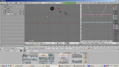
We have animated the basic bounce. On Frame 12, we will squash the ball. Go to Frame 12. Place the cursor at the base of the lattice. Set the Pivot point to 3d Cursor. Scale the ball on the Z axis by pressing the S key and then the Z key. Press I to insert a LocRotScale key.
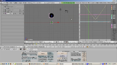
In IPO window, move the Green vertical bar back and forth to scrub the animation. We have now animated both the bounce and the squash. Pressing Alt A will also do the animation of the bounce forever. Press Esc to stop the animation.
The reason the ball bounces forever is that the animation is 23 frames long, exactly as long as the ball bounce. That's a coincidence. To demonstrate this, change the animation length to 250 frames. and press Alt A. Now the ball bounces and just stays there from frame 24 to 250 instead of bouncing. Suppose we want the ball to bounce forever no matter how long the animation. To do that, go to the IPO window. Press A to select all the curves. From the Curve Menu, select Extend Mode and select Cyclic. When you replay the animation, Alt A, the ball bounces for the entire animation.
There's plenty more tweaking that can be done to this basic animation. You can add materials and textures to the ball. You can play with the IPO curves to control how the ball moves, stretches, and contracts. I hope this gets you started. Happy blending.
At first glance, one might think that animating a bouncing ball would be easy, a simple matter of moving a sphere and adding location keyframes. Sure, the ball would move. However, it would not bounce realistically. Because of gravity, the ball moves slower at the top than at the bottom. The ball actually is stretched a bit in the middle of the bounce and squashes when it hits the floor. Because of friction, the height of the next bounce is less than the height of the previous bounce. The spin of the ball must be realistic as well.
We're not going to address all these things. The purpose of this tutorial, which is based on the Blender 3D Noob To Pro bouncing ball tutorial, is to show the basics of animating a bouncing ball, including squashing the ball using lattice deformation and how to use IPO curves to bounce the ball a number of times without redoing the first bounce sequence again and again. I used Blender 2.49B.
We'll start by deleting the default cube (Right click, pressing the X key, and confirming the delete). Then add a UV Sphere (Space-Add-Mesh-UVSphere), accepting the default settings of 32 rings and 32 segments. From the editing buttons (F9), press Set Smooth. Then add a subsurf modifier at level 2. This gives us a nice round ball.

Press Num1 to go into Front View. Add a Lattice (Space-Add-Lattice). Press Z to go into wireframe mode. Select the lattice. Scale the lattice so that the UV Sphere is inside of it, with the sides of the lattice touching the sides of the sphere.

To make the lattice control the sphere, select the sphere, then Shift Select the lattice. Press Control-P and choose the Lattice Deform option to make the lattice the parent of the sphere. Select the UV Sphere and press F9. Look at the modifier stack. You should see the phrase "Lattice parent deform" at the top of the stack. This means that the lattice modifier was applied correctly. To test this, select the lattice and scale or move it. The sphere mesh should scale or move as well. We'll use the lattice later to squash the ball. The Make Real button would make the lattice permanently control the ball. We can ignore this button for this simple tutorial.
Now it's time to animate the ball. To do this, switch to Scene SR:1-Animation. This built in scene setup has all the windows we need for animation - the Outline Window, the 3D viewport of course, the IPO window, which we'll use later, and the buttons window.

Position the 3D cursor in the 3D viewport and press Num1 to go to Front View. The blue Z arrow should point upwards. We're going to animate the first bounce over 23 frames, which is about 1 second assuming a standard movie speed of 24 frames per second. Press F10 to go to the Scene buttons, and set the end frame to 23.
It's time to insert key frames. Note that we are animating the lattice, not the ball.
Make sure we're in Frame 1. If not, press Shift-Left Arrow or enter the number 1 in the Frame Number area. We start the animation when the ball is at the top of its bounce. Press the G key, then the Z key, to move the lattice up in the Z direction, about 7 blender units or so, to the top of the bounce.
Press the I key and set a key for LocRotScale. Note how there are now 9 curves in the IPO window, for location, rotation, and scale, in the X, Y, and Z direction. You get 3 curves for each, for X, Y, and Z.
Go to Frame 11. Press the G key, then the Z key. Mgzove the lattice down in the Z direction, to 1 Blender unit above the ground. This is where the ball will be squashed a bit. Press the I key and insert a LocRotScale key.
Go to Frame 13. Leave the Lattice in the same position and insert another LocRotScale key.
Go to Frame 23. Move the Lattice back to its position at Frame 1 by pressing the G key, then the Z key, then moving it back to 7 Blender Units up. In real life, the ball should move back somewhat less than that, because of friction, but for this tutorial, where the ball will just bounce forever, we can ignore this. Press I and insert a LocRotScale key.

We have animated the basic bounce. On Frame 12, we will squash the ball. Go to Frame 12. Place the cursor at the base of the lattice. Set the Pivot point to 3d Cursor. Scale the ball on the Z axis by pressing the S key and then the Z key. Press I to insert a LocRotScale key.

In IPO window, move the Green vertical bar back and forth to scrub the animation. We have now animated both the bounce and the squash. Pressing Alt A will also do the animation of the bounce forever. Press Esc to stop the animation.
The reason the ball bounces forever is that the animation is 23 frames long, exactly as long as the ball bounce. That's a coincidence. To demonstrate this, change the animation length to 250 frames. and press Alt A. Now the ball bounces and just stays there from frame 24 to 250 instead of bouncing. Suppose we want the ball to bounce forever no matter how long the animation. To do that, go to the IPO window. Press A to select all the curves. From the Curve Menu, select Extend Mode and select Cyclic. When you replay the animation, Alt A, the ball bounces for the entire animation.
There's plenty more tweaking that can be done to this basic animation. You can add materials and textures to the ball. You can play with the IPO curves to control how the ball moves, stretches, and contracts. I hope this gets you started. Happy blending.
Saturday, October 10, 2009
Blender Community Toolbar
Hi. I'm Ira Krakow. The purpose of this video is to make you aware of a fantastic resource which I think is an essential tool for any Blender user, from newbie to seasoned professional. It's called the Blender Community Toolbar.
The Toolbar installs in seconds on your browser. There are versions for Internet Explorer, Firefox (the one I use because I like open source), and Safari (the Apple Macintosh browser). I also want to point out some of the links that I have found useful. This is just one person's favorites list, and certainly it's not an exhaustive one. Blender has a large and enthusiastic worldwide following of extremely talented people who volunteer their time and knowledge to enrich the experience of working in Blender for all of us.
So let's start with Kernon Dillon, the author of the Blender Community Toolbar and developer of Blendernewbies.com. First, I want to publicly thank Kernon for all the hard work he's put into blendernewbies. Kernon's clear, precise, and even tempered presentations of even the most difficult Blender topics are a pleasure to watch. Two of my all time favorites are:
A five part tutorial on modeling oven baked pretzels in Blender, which describes just about everything about how to make the pretzels in such a way that you can smell the pretzels baking in the oven.
A three part tutorial on making a magic wand with Blender particles.
I'm not alone as a member of Kernon's fan club. You can read Kernon Dillon, A Blender Community Treasure.
Now we'll do a quick tour of the toolbar. At the extreme left is a button with the Blender icon. Click on that and you'll get to the official Blender Web site, blender.org. This is the place to check out the official Blender news, straight from the source. You can download the latest version (2.49b), learn about Elephant's Dream, Big Buck Bunny, and YoFrankie, the Blender open source movie projects, as well as Durian, the latest Blender open source movie, coming soon to your local computer. You can also access Blender's documentation, the wiki, and catch up on the news from BlenderNation.com, another great place to find out what's going on in the world of Blender.
If you're new to Blender, check out the Blender Basics Video Tutorial link, which gets you to BlenderUnderground.com's excellent 5 Part Blender Basics video tutorial. Blenderunderground.com, lead by Apollos, goes beyond the basics, looking inside the hood to show us how Blender actually operates. The philosophy is that to be efficient in Blender you need to know how Blender works, not just mindlessly pressing keystrokes to get a particular effect. My favorites are:
Part 4, especially the discussion of the outliner. After viewing this, you'll know why you need to create a material before you create a texture, or the difference between an object and its data.
and
Part 5, which has an in depth discussion of lighting, shaders, ray tracing, and other good stuff.
The next button has links to tutorials, from the beginner to the advanced level. One I found very useful is the Introduction to Character Animation. This was part of the Blender Summer of Documentation project. If you can master this tutorial, you will be well on your way to understanding how to animate a character in Blender.
The Extras tab contains many links to Blender resources that should give you many ideas. One link I like is the Blender Open Material Repository. It's a database of over 600 materials, ready for use in your Blender projects.
If you want to extend Blender with Python scripts, you can check out How To Use Python Scripts in Blender, as well as the many Python scripts available for download from the toolbar.
The most fun area of the Community Toolbar is the RSS feeds. You can catch up on news from all sorts of sources. As you can see I have over 400 unread articles. Staying up to date with Blender takes just about a 24 hour, 7 days a week, 365 days a year proposition.
I certainly would follow the articles in Blenderartists.org closely. Blenderartists.org is the most popular site for Blender users, as opposed to Blender.org, which is more geared to Blender developers. The toolbar also includes the feed for Blendernation, just another way to keep up with developments. If you want to see how Blender 2.5 is progressing, follow the Blender Development and the Blender Development Log feeds. And to download the latest version of 2.5, follow the graphicall.org feed. What's nice is that the RSS feeds are updated as soon as new content is added, so you'll always be up to date.
Obviously a short video like this cannot get to all the fantastic resources available from the Blender Community Toolbar. I hope I have encouraged you to download it and see for yourself. Happy Blending!
Tuesday, September 22, 2009
2.5 Pivot Points
Hi. The goal of this video is to get you comfortable moving around in Blender 2.5. If you're going to continue with Blender, 2.5 will be your new home. The developers just made 2.5 the official "trunk" for Blender development. That means that future development will be exclusively in 2.5. Work on older versions will, most likely, be limited to bug fixes and, as 2.5 becomes the standard.
Scaling and rotating objects are a fundamental Blender skill. The pivot point defines how objects will be rotated and scaled. If you're relatively new to Blender, you can easily get objects moving in ways you might not expect. As we progress, I will point out differences between Blender 2.5 and the older versions. The pivoting actions really haven't changed in 2.5. However, some cosmetic things like the default color of the active object and the icons for rotation and scaling, have changed. You should feel very comfortable pivoting your way in 2.5 almost immediately.
We start with the default Blender scene. First, we delete the default cube. Before, you could either use the delete key or press X. In 2.5, only X works. The delete key does nothing. So press X and confirm the delete.
We'll add the monkey object, by pressing the SPACE key. Something happens, but it's not what you expect. You get a different menu than before, a menu that has nothing to do with adding objects. Press ESC. We'll save discussion of that menu for another time. Instead, press Shift-A, which is the keyboard shortcut for adding objects. Shift-A brings up the familiar object add menu. Select Add-Mesh-Monkey, as before.
Let's look at the outliner window, in the upper right corner of the screen, and scroll down. Guess what? Suzanne isn't there. She has been renamed "Mesh". I guess they'll have to rename the Suzanne Award.
We'll create 3 monkey objects to demonstrate rotation. First, duplicate our monkey - it will take a bit of time getting used to the name "Mesh" - with Shift-D. Shift-D works as before. We grab the copy and move it away from the original, and left click to confirm. Then we press Shift-D to create another copy and drag it to form a triangle of monkeys.
Switch to Quad View, a new built in view, by going to the View menu, and selecting Toggle Quad View. The window is divided into 4 windows, Top, Front, Right, and Camera, that make it, in my opinion, much easier to navigate around your scene than before. Since Toggle Quad View is a toggle, by selecting Toggle Quad View again, you get back to the startup scene, with just one 3D window.
We'll work in Quad View. Adjust the monkeys positions so that they look right in Top View and Camera View. We'll work in Top View. Select the first monkey with right click. Then hold down the Shift key, Right Click, and select the second monkey. Hold down the Shift key, Right click, and select the third monkey. Note that the default color for the selected object and the active object - the last one you selected, and the name that displays in the lower left hand corner - has changed from pink to orange. I think orange is much easier to see. The active object has a light orange border, as opposed the light pink in the older Blender versions.
The default pivot mode is Bounding Box center, which means that the pivot point is defined by the bounding box. The Move Object Centers Only is off by default, as before. Press the R key to rotate the monkeys. Note that the rotation icon is double arrows, and that the monkeys rotate around the bounding box center. Pressing Escape cancels the rotation, as before.
Just for fun, press the R key twice (R and R). This allows you to rotate in 3 dimensions. It's a neat feature and not very well known. Press Esc to cancel.
Turn the Move Object Centers button on. This makes rotation and scaling affect the object center only, not the objects themselves. Now press the R key and rotate. The monkeys do not tilt as they rotate. Press Esc to cancel the rotation, and turn off the Move Object Centers Only button.
Now press S to scale. With the Move Object Centers Only button inactive, all the monkeys grow or shrink. Press Esc to cancel the scaling. Now turn on the Move Object Centers Only button and press the S key. Now, the monkeys don't grow or shrink, BUT they do get nearer or farther away from each other while preserving their relative position. This is useful for repositioning objects in your scene. Press Esc and turn off the Move Object Centers Only button.
Now open the Pivot Menu and select Active Object as your pivot point. Press R to rotate. Now the monkeys tilt while they rotate around the active object, similar to the bounding box behavior. Press Escape to cancel.
Turn on the Move Object Centers Only button and press the R key. Now the monkeys keep facing forward as they rotate around the active object. Press Esc to cancel the rotation, and turn off Move Object Centers Only.
Press the S key to scale. The monkeys grow and shrink. Press ESC to cancel the scaling. Turn on the Move Object Centers Only button and press the S key. Now the monkeys move away from or closer to each other but do not grow or shrink. Press ESC to cancel. Turn off the Move Object Centers Only button.
Open up the Pivot Menu and select Individual Centers as your pivot point. Press R to rotate. Each monkey rotates around its center point. Press Esc and turn on the Move Object Centers button. Now when you press R to rotate, nothing happens. That's because only the centers (all 3 of them) rotate. The monkeys don't do anything. Press Esc to cancel.
Turn off the Move Object Centers button and press S to scale. Now the monkeys grow and shrink in unison, like a dance line. Press Esc to cancel and turn on the Move Object Centers button. Again, the monkeys don't do anything because only the centers scale, and each of them is only a point to begin with. Press Esc to cancel and turn off the Move Object Centers button.
Open up the Pivot Menu and select 3D Cursor as your pivot point. The behavior of rotation and scaling is the same as for Bounding Box and Active Object, except that the pivot is around wherever the 3D cursor is situated.
Our final pivot point type, Median Point, is the center point for all the selected objects. This is similar to Bounding Box center, except that the median point might be, and usually is, different from the bounding box center because objects tend to have different sizes. As you see, the behavior is similar, but the pivot point is slightly different.
To summarize, pivoting is basically the same as before. However, because of the new Quad View, the better choice of colors and icons, and the improved design of the startup screen, it's much easier to see what's going on.
Wednesday, September 16, 2009
2.5 User Preferences
I ran the pre-alpha version of Blender 2.5, as of September 15, 2009. You see the startup screen first, then I switch to the User Preferences window. After that, I hover over each menu item long enough for the tooltip to display. If there is a menu choice, I click to display all the choices. Remember, this is pre-alpha software. No guarantees that each and every feature will make it into the final 2.5 release, but this should give you an idea about what the developers goals are. I apologize if you're not a speed reader. You might want to pause the video often, read the tooltips you're interested in, and continue.
Tuesday, September 15, 2009
2.5 Sneak Preview
I played around with a recent build (878-361, to be exact) of Blender 2.5. Blender 2.5 is a major rewrite of Blender which, in my opinion, makes Blender's great user interface and experience even greater. I'd like to give you a quick tour of the startup windows and the menus, to give you a sneak peek at Blender's makeover. Blender's new look is very exciting.
Please remember that we're looking at 2.5 in its embryonic stage. It's not even in its pre-release stage. Not all the features we see may make it into the final release. However, there's enough to explore so that we can get a general idea of what 2.5 will ultimately look like. I'm not going to try to build anything, or see whether any of the menu choices work. I just want to give you a quick peek of 2.5, under the hood.
So let's get started.
Here's the Blender 2.5 startup screen. Right off the bat, you'll notice a few changes. First, the Buttons Window is gone, replaced by the Timeline. Second, the 3D Viewport, defaults to a User Perspective view, as opposed to Top View in earlier versions. In the 2.5 view, you actually can see the cube as a cube, aligned along the grid.
Some things are the same. We still have the same 3 default object, the camera, the lamp, and the default cube. You can verify that because a small outline view window is in the upper right corner of the screen. Scrolling down will show you that the three objects are indeed in the scene.
Look at the User Preferences menu, which has changed somewhat. Gone are the Timeline and the Game menus. We have 4 menu items, File, Add, Render, and Help. So is the dropdown with the 5 default screen styles. This is replaced by a menu with the default Screen, called, appropriately, Screen. You can create your custom screens by pressing the + key, which adds a screen named Screen.001. You can delete the Screen by pressing the X key right next to it.
The default scene is called Scene, as in 2.4x Blender versions. You can click on the + button to add a scene - a change from selecting Add New.
A new menu lets you select among different rendering engines. The default, as it was before, is Blender's internal renderer. You now can select Blender Game, Povray, or install another renderer, which should (I'm only speculating) make the Engine menu item selectable.
A new "jobs timer" has been added.
The information about vertices, faces, objects, layers, memory, and so on, has not changed.
I mentioned the small outliner window earlier. You can use the scroll bar or press Ctrl - down arrow (as before) to toggle this window (or any window, for that matter) .
The panel at the lower right contains a number of menus. These menus change depending on the context you're in. The default is the scene panel, which has the buttons you need that are relevant to rendering the current scene.
These used to be part of the World buttons. If you click on the All Scenes dropdown, these buttons can apply to other collections of scenes and other data.
The menus are collapsable. Press the arrow to expand or contract. You can get full expansion or full contraction. Fully collapsed into groups, the scene groups are: Render, Layers, Dimensions, Anti Aliasing, Shading, Output, Performance, Post Processing, Stamp, and Units. The groupings have changed from the old World settngs. Look at Output, for example.
At the bottom is a group of icons that let you toggle among different button settings. The default is the camera icon, for the scene. Next is World, which has the menu choices that are more global - Preview, World, Ambient Occlusion, Mist, and Stars.
The Object buttons are Transform, Relations, Groups, Display, Duplication, and Animation. Note that the default name of the cube, which is selected by default, is NameCube - no doubt, to encourage you to actually name your objects - a good habit to get into. These buttons control aspects of the selected object. Look at Transform, which controls location, rotation, and scale. Note that X, Y, and Z are assumed, so LocX, LocY and LocZ labels are gone.
Next are Constraints. From the dropdown, you can add the constraints shown.
Next are the Object Data buttons, grouped into Normals, Vertex Groups, Shape Keys, UV Texture, and Vertex Colors.
Next are the Modifiers. The modifiers are grouped into an easy to read 3 column list.
Next to last are the Material buttons, with the groups you see.
Finally, there are the Texture buttons.
Each window has, at its lower left corner, a menu from where you can change its type. We'll go to the Timeline window, which currently has its menu bar displayed, and click on its window type icon. A few changes, right off the top: the Scripts Window has been renamed Console, User Preferences has been renamed Info, and the Action Editor has been renamed Dopesheet. I'm sure there are other changes.
I hope you enjoyed our sneak preview of Blender 2.5. It looks like the best is only going to get better. So happy Blending and see you next time.
Subscribe to:
Posts (Atom)